
What is Metal Injection Molding (MIM)?
Metal Injection Molding (MIM) is a manufacturing process that combines plastic injection molding precision with the strength of metal, enabling the production of small, complex, high-performance metal parts that are difficult or costly to make via machining or casting.
It is widely used in industries such as medical devices, electronics, automotive, and firearms, where high precision, tight tolerances, and repeatability are required.
MIM is ideal for intricate geometries and supports materials like stainless steel, titanium, and other high-performance alloys. It is also cost-effective for high-volume production due to reduced machining waste and minimal manual processing.
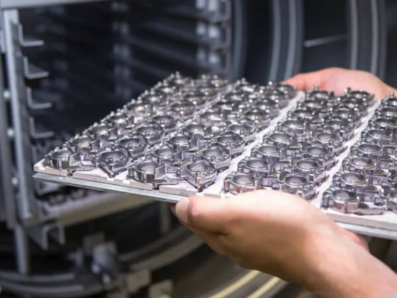
The process starts by mixing fine metal powders (typically <20 μm) with a binder system to create a feedstock that flows like plastic (about 60:40 metal-to-binder ratio). Manufacturers inject this feedstock into a mold to form a green part, carefully controlling parameters such as temperature, pressure, and injection speed to avoid defects like air entrapment or sink marks.
After molding, the part undergoes debinding to remove the binder, followed by sintering to densify the metal and achieve final strength and dimensional accuracy.
Manufacturers use MIM best for producing small to medium precision components with thin walls (down to ~1 mm) and complex shapes that conventional metalworking methods cannot easily achieve.
How Does the Metal Injection Molding Process Work?
The Metal Injection Molding (MIM) process consists of several stages that transform fine metal powders into precise, solid metal components. It is widely used for small, complex metal parts where traditional methods like machining or casting are less efficient.
Feedstock Preparation
The process starts with blending fine metal powders with a thermoplastic binder to produce a uniform feedstock. The binder allows the powder to flow into the mold and maintains the shape during molding. The mixture is then granulated into small pellets, ensuring consistent handling and repeatable part quality. Typical metal-to-binder ratios are near 60:40, providing flowability while retaining metallic properties.
Injection Molding
The feedstock is heated and injected under high pressure into a precision mold cavity, forming a “green part.” This stage defines the part’s geometry and internal features. Accurate control of temperature, pressure, injection speed, and holding time is essential to prevent defects such as voids, sink marks, or incomplete filling. The mold is designed to allow intricate shapes, thin walls, and tight tolerances similar to plastic injection molding.
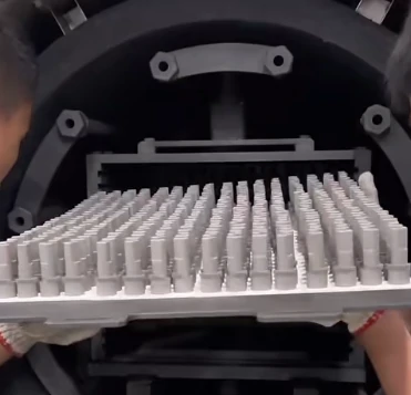
Debinding
After molding, most of the binder is removed to create a brown part. This is done using one of several methods:
- Thermal debinding– heating the part to gradually vaporize the binder
- Solvent debinding– dissolving the binder in a chemical solution
- Catalytic debinding– breaking down the binder under acidic conditions
The brown part retains its shape but is porous and has limited mechanical strength. Proper debinding is critical to prevent defects and prepare the part for sintering.
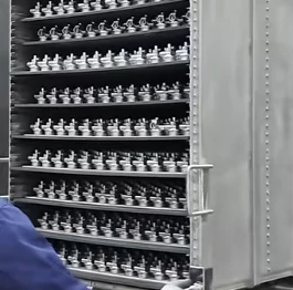
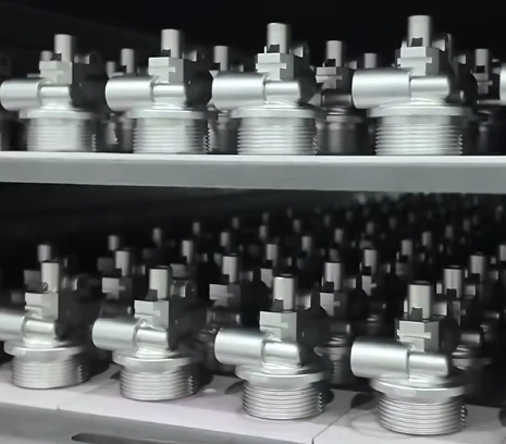
Sintering
The brown part is heated in a controlled atmosphere furnace to fuse the metal particles together without melting the material completely. During sintering:
- The part shrinksto its final dimensions
- Density increases, producing a solid metal component
- Mechanical properties such as strength, hardness, and dimensional accuracyare established
Sintering ensures that the final part meets the required specifications and retains the complex features of the mold.
Optional Post-Processing
Depending on application requirements, sintered parts may undergo additional steps such as machining, heat treatment, or surface finishing to meet precise tolerances or performance standards. These processes are applied selectively to enhance part functionality or aesthetics.
What Materials Are Used in Metal Injection Molding?
Metal Injection Molding (MIM) is compatible with a wide and growing range of metals and alloys, allowing designers to select materials that meet specific performance and application requirements. The versatility of MIM enables the production of components across industries such as medical, aerospace, automotive, and industrial manufacturing.
Stainless Steels (SS)
Stainless steels are widely used in Metal Injection Molding (MIM) for their corrosion resistance, strength, and durability. Common grades include:
- 316L– Resistant to corrosion, often used in medical implants and marine applications.
- 17-4 PH– High strength and hardness, suitable for aerospace components and firearms.
These steels ensure long-term performance in demanding environments.
Low-Alloy Steels
Low-alloy steels offer a balance of strength, toughness, and wear resistance, making them suitable for automotive and industrial applications. Examples include:
- Fe-2Ni and Fe-8Ni– Common in automotive and machinery components.
- 42CrMo4– Provides high toughness and wear resistance for heavy-duty applications.
Tool Steels
Manufacturers employ tool steels such as M2 and D2 in MIM to produce components that require high hardness, wear resistance, and durability, including cutting tools, mold inserts, and industrial dies.
Superalloys
These alloys resist hot oxidation and flake formation, making them ideal for combustion-related parts.
Titanium and Titanium Alloys
Titanium alloys, such as Ti-6Al-4V, are valued in Metal Injection Molding (MIM) for being lightweight, corrosion-resistant, and biocompatible. Applications include medical implants, aerospace structures, and high-performance sporting goods. Titanium processing in MIM requires careful control during debinding and sintering to maintain its mechanical properties.
Copper and Precious Metals
Nickel-Based Alloys
Manufacturers select nickel alloys, including Inconel, for their high-temperature resistance and strength, making them suitable for aerospace, power generation, and chemical processing applications where extreme conditions exist.
Aluminum Alloys
Certain aluminum alloys such as 6061 and 7075 can be processed using MIM in specialized cases. However, aluminum requires non-standard sintering conditions, making its use less common compared to steels and superalloys.
Iron-Carbon Alloys
Iron-carbon alloys provide good machinability and strength, often used in automotive components, industrial gears, and valves. They are suitable for MIM parts where performance and cost-efficiency must be balanced.
Summary Table: Material Categories and Benefits
| Material Category | Examples | Key Benefits |
| Ferrous Alloys | Stainless steels, low-alloy steels, carbon steels | Strength, toughness, corrosion resistance (varies by grade) |
| Non-Ferrous Alloys | Superalloys (Inconel), Titanium alloys, Copper, Precious metals | High corrosion and heat resistance, thermal conductivity, lightweight, biocompatibility |
Selecting the right material for Metal Injection Molding (MIM) is essential to achieve the desired balance of strength, precision, and cost-effectiveness. Material choice directly impacts mechanical performance, process efficiency, and component reliability across applications.
Which Material Is Best for Metal Injection Molding?
Selecting the most suitable Metal Injection Molding (MIM) materials requires balancing mechanical performance, environmental resistance, and overall cost. The optimal choice depends on how the part will be used rather than a single universal rule.
Core selection criteria
| Factor | Key considerations |
| Mechanical properties | Strength, hardness, wear resistance |
| Environmental resistance | Corrosion, temperature, chemical exposure |
| Total cost | Material price, processing complexity |
This framework helps evaluate MIM material selection in a structured way, avoiding unnecessary over-specification.
Mechanical and environmental requirements
The first step in Metal Injection Molding (MIM) material selection is defining the working conditions of the part. Manufacturers require high strength, hardness, corrosion resistance, or temperature stability depending on the application, but they cannot maximize all properties at the same cost level.
For example, manufacturers widely use 17-4PH stainless steel in MIM applications for its high strength and hardness, which they can enhance through precipitation hardening. It is well suited for load-bearing and high-stress components.
In contrast, 316L stainless steel for MIM parts offers excellent corrosion resistance, making it ideal for medical and marine environments.
Comparison of common stainless steels
| Property | 17-4PH Stainless Steel | 316L Stainless Steel |
| Main advantage | High strength & hardness | Superior corrosion resistance |
| Tensile strength | 高い | Moderate |
| Corrosion resistance | Good | Excellent |
| 熱処理 | Yes | No |
| Typical applications | Industrial tools, automotive, aerospace | Medical, marine, food-related parts |
Cost and process considerations
Cost plays a major role in Metal Injection Molding (MIM) material selection. 17-4PH stainless steel typically requires additional heat treatment, increasing total processing cost. In contrast, 316L stainless steel often avoids this step, simplifying production and reducing cost. The final decision depends on whether performance gains justify the added expense.
Beyond stainless steels, other materials are also used in MIM applications depending on requirements:
- Titanium alloys (Ti-6Al-4V in MIM): Lightweight, high strength-to-weight ratio, used in aerospace and medical implants, but require controlled processing conditions and are more expensive.
- Tool steel (M2 in MIM applications): Offers excellent wear resistance and toughness, suitable for industrial tooling, but is more difficult and costly to process.
Which Metal Alloys Are Compatible with Metal Injection Molding (MIM)?
Metal Injection Molding (MIM) is compatible with a wide variety of metal alloys for MIM applications, and this material flexibility is one of the key reasons for its broad industrial adoption. Manufacturers generally group these materials into three main categories, each offering distinct performance characteristics for different use cases.
Ferrous Alloys
Manufacturers widely use ferrous alloys in Metal Injection Molding (MIM) as the most common material family. They design these iron-based alloys to balance strength, hardness, and cost efficiency, making them suitable for large-scale production.
- Common examples include stainless steels such as 17-4PH MIM stainless steeland 316L MIM stainless steel.
17-4PH offers high strength and good corrosion resistance.
316L provides excellent corrosion resistance, making it suitable for demanding environments.
- Tool steels in MIM applicationsare also widely used due to their high hardness and wear resistance, especially for precision tooling and durable mechanical parts.
Typical applications include automotive components, industrial tools, and mechanical systems requiring durability.
Non-Ferrous Alloys
Manufacturers select non-ferrous alloys in Metal Injection Molding (MIM) when applications require properties such as low weight, corrosion resistance, or high conductivity.
- Titanium alloys in MIMare valued for their high strength-to-weight ratio and biocompatibility, making them suitable for medical and aerospace-related applications.
- Copper alloys in MIMprovide excellent electrical and thermal conductivity, commonly used in electronic connectors, heat transfer components, and precision conductive parts.
These materials are often chosen for performance-driven applications where ferrous alloys are not suitable.
Specialty Alloys
Manufacturers design specialty alloys for Metal Injection Molding (MIM) to meet extreme operating conditions, including high temperature, high stress, or specialized functional requirements.
- Superalloys in MIM componentsare used in high-temperature environments such as turbine systems.
- Tungsten heavy alloys in MIMare known for very high density, often used in radiation shielding and vibration control.
- Cobalt-chrome (Co-Cr) alloys in MIMoffer excellent wear resistance and biocompatibility, commonly used in medical implant applications.
Which Part Geometries Work Best for Metal Injection Molding (MIM)?
Metal Injection Molding (MIM) is not designed as a universal manufacturing method. Instead, it performs best with a specific range of complex metal part geometries in MIM where conventional processes such as machining or casting become inefficient or costly.
The ideal application range
The most suitable candidates for Metal Injection Molding (MIM) parts are typically small components, usually under 100g in weight, with highly detailed and three-dimensional structures. These are often parts that are difficult to machine due to tool access limitations or excessive processing time.
Key geometry characteristics
Manufacturers generally consider the following features ideal for MIM part design requirements:
| 機能 | Ideal Condition for MIM |
| Size | Small parts (< 100g) |
| 複雑 | High-detail structures |
| Geometry | 3D, non-symmetrical shapes |
| Production volume | High-volume manufacturing |
Why complexity favors MIM
A major advantage of Metal Injection Molding (MIM) is its efficiency in handling complexity. In CNC machining, every additional feature increases cost and production time. In contrast, once the mold is developed in MIM, geometric complexity has minimal impact on per-part cost.
Although manufacturers require a relatively high initial tooling investment for MIM manufacturing, the process becomes highly cost-effective in large production runs where they produce thousands of identical parts.This makes it especially suitable for mass production of intricate components.
Typical geometry applications
Common Metal Injection Molding (MIM) geometry applications include:
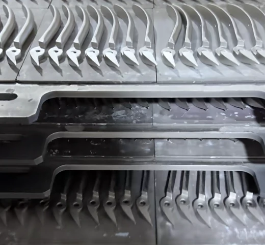
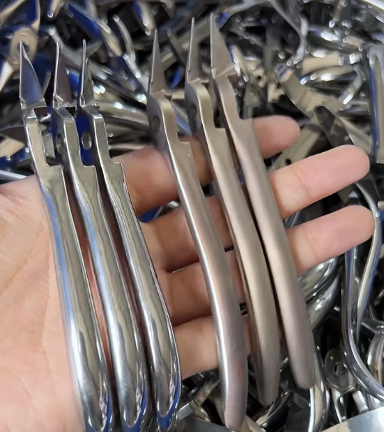
- Firearms components in MIMsuch as triggers, hammers, and sights with fine internal details
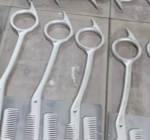
- Medical MIM components including surgical tools and orthodontic brackets requiring miniaturized precision
- Electronic MIM parts such as connectors and heat sinks with thin walls and internal channels
- Automotive MIM components like sensor housings, micro gears, threads, and parts with undercuts
These geometries are often too complex or expensive to manufacture using traditional methods at scale, but Metal Injection Molding (MIM) enables stable, repeatable, and cost-efficient production.
What Machine Types Are Used for Metal Injection Molding (MIM)?
The type of machine in Metal Injection Molding (MIM) plays a crucial role in production performance, affecting precision, efficiency, and overall part quality. MIM machines are typically classified into three main categories based on their drive systems.
Hydraulic MIM Machines
Hydraulic MIM machines use hydraulic fluid to generate force. Manufacturers design them for high power and robustness, making them suitable for parts that require strong injection force. However, hydraulic MIM machines have lower precision compared with electric systems, and performance can vary with temperature changes in the hydraulic fluid. They also consume continuous energy to maintain pressure, increasing operational costs.
Electric MIM Machines
Electric MIM machines employ servo motors to drive all major movements. They provide high precision and repeatability in MIM, ideal for components with tight tolerances, such as medical or aerospace MIM parts. Electric machines are more energy-efficient because they only consume power during movement and require less maintenance due to the absence of hydraulic fluids, pumps, and filters.
Hybrid MIM Machines
Hybrid MIM machines combine features of both hydraulic and electric systems. Typically, clamping is powered hydraulically while injection is driven electrically. This provides a balanced performance in MIM production, offering better precision than hydraulic-only systems and higher power than purely electric machines.
| Machine Type | Primary Drive | Key Advantage |
| Hydraulic | Hydraulic fluid | High power |
| Electric | Servo motors | High precision |
| Hybrid | Mixed | Balanced performance |
Selecting the right MIM machine depends on the specific requirements of the part, balancing cost, precision, energy efficiency, and production speed. Electric machines excel in accuracy and energy savings, hydraulic machines provide strong injection force at a lower initial cost, and hybrid machines offer a compromise for versatile applications.
How are common Metal Injection Molding (MIM) part defects categorized
Understanding Metal Injection Molding (MIM) defects is essential for effective quality control in MIM parts. A practical way to manage defects is by grouping them according to the process stage in MIM, which simplifies troubleshooting and helps identify the root cause efficiently.
Defects by MIM Process Stage
Common Metal Injection Molding part defects can be divided into three main categories:
| MIM Stage | Typical Defects |
| Molding | Short shots, flash, weld lines |
| Debinding | Cracks, slumping, blistering |
| Sintering | Distortion, porosity, dimensional inaccuracy |
Categorizing defects in this way allows manufacturers to trace issues back to the exact step where they originated, avoiding unnecessary adjustments to unrelated parameters.
Why process-based categorization matters
A flaw visible in the final sintered MIM part often begins in an earlier stage. For instance, a crack appearing after sintering may result from overly aggressive binder removal during debinding rather than a sintering error. Recognizing the interconnected nature of MIM process stages ensures that corrective actions target the real cause.
- Molding issues like inconsistent green part density can lead to distortion in later stages.
- Debinding problems, such as residual binder, may cause blistering during sintering.
- Sintering errors, including incorrect temperature profiles, can reduce mechanical performance.
By classifying Metal Injection Molding defects by molding, debinding, and sintering stages, manufacturers can implement a structured troubleshooting framework. This approach ensures consistent MIM part quality and minimizes costly repeat errors.
What Design Considerations Are Needed for Metal Injection Molding?
Designing components for Metal Injection Molding (MIM) requires aligning geometry, material behavior, and process constraints from both injection molding and powder sintering stages. A successful design does not only focus on final shape accuracy but also on how the part behaves throughout molding, debinding, and sintering to maintain dimensional stability and cost efficiency.
Shrinkage Control in Metal Injection Molding (MIM)
One of the most critical factors in Metal Injection Molding (MIM) is sintering shrinkage. During thermal densification, parts typically contract by 15–20%, depending on material and geometry.
To achieve dimensional accuracy, this shrinkage must be compensated directly in the mold design stage. Complex geometries may also experience uneven contraction, known as anisotropic shrinkage, where different axes shrink at different rates. If not properly accounted for, this can lead to dimensional distortion or tolerance deviation.
Wall Thickness Optimization in Metal Injection Molding (MIM)
Maintaining consistent wall thickness is essential for stable feedstock flow during injection and uniform densification during sintering. In Metal Injection Molding (MIM), variations in thickness often result in internal stress imbalance.
- Thin sections may cause incomplete cavity filling or weak structural integrity
- Thick sections can lead to uneven shrinkage or deformation during sintering
A balanced wall design ensures smoother material flow, reduces internal defects, and improves overall part stability.
Draft Angles and Ejection Performance
Similar to plastic molding, draft angles play a key role in Metal Injection Molding (MIM) for smooth demolding of the green part.
Proper draft design reduces friction between the cavity wall and molded part, minimizing surface damage during ejection. Additionally, incorporating smooth transitions and corner radii helps reduce stress concentration, lowering the risk of cracking during both handling and sintering.
Designing Complex Geometries in Metal Injection Molding (MIM)
One of the major advantages of Metal Injection Molding (MIM) is its capability to produce highly intricate shapes that are difficult or uneconomical to machine.
However, complexity must be balanced with manufacturability. Features such as undercuts, deep ribs, threads, and sharp internal corners can increase tooling difficulty and affect part integrity during sintering. Strategic simplification or design modification is often required to ensure process reliability.
Sintering Behavior and Post-Processing Considerations
Sintering is the most influential stage in Metal Injection Molding (MIM), as it defines final density, strength, and dimensional accuracy.
During sintering:
- Unsupported long spans may deform under gravity
- Sudden thickness transitions can create stress concentration and cracking
- Internal cavities may trap gases, leading to defects
To mitigate these risks, designers may incorporate temporary supports, adjust part orientation, or redesign geometry for self-supporting stability.
In addition, parts requiring tight tolerances or enhanced surface quality often undergo secondary operations such as machining or polishing. These should be considered early in the design phase to balance cost and performance requirements.
Tooling Structure and Design Flexibility in MIM
A typical Metal Injection Molding (MIM) mold consists of two primary halves forming a sealed cavity. The core defines internal features, while the cavity forms external geometry. Ejector pins are used to release the solidified green part after molding.
For more complex designs, slides and additional core mechanisms—similar to those used in plastic injection molding—can be integrated. While these enhancements expand design freedom and reduce downstream assembly, they also increase tooling cost and engineering complexity. Therefore, a careful cost–benefit evaluation is necessary at the design stage.
Key Design Balance in Metal Injection Molding (MIM)
Effective Metal Injection Molding (MIM) design requires balancing manufacturability, cost, and performance. Core considerations include:
- Controlling shrinkage during sintering
- Maintaining uniform wall thickness
- Optimizing draft angles and radii
- Managing sintering deformation risks
- Evaluating tooling complexity versus production efficiency
When these principles are properly integrated, MIM can deliver highly complex, high-precision metal components with minimal post-processing requirements.
How Is MIM Tooling Different from Plastic Injection Molding Tooling?
Although Metal Injection Molding (MIM) and plastic molding sound similar, the tooling for MIM is fundamentally different due to the unique properties of MIM feedstock and the high demands of the process.
| 機能 | MIM Tooling Requirement | Plastic Tooling Requirement |
| Tool Steel | Hardened, wear-resistant steel | Standard, softer steel |
| Ejection | Robust and precise system for fragile parts | Standard ejection system |
| Shrinkage | Designed for 15–25% shrinkage | Designed for 0.5–5% shrinkage |
Tool Steel: Built to Resist Abrasion
The MIM feedstock, composed of fine metal powders and a polymer binder, is highly abrasive compared with any filled plastic. As a result, MIM molds require hardened, wear-resistant tool steels such as D2, M2, or carbide inserts in high-wear areas. This ensures long tool life and maintains dimensional accuracy throughout the production cycle.
Ejection Systems: Protecting Fragile Green Parts
After molding, MIM parts are in a fragile “green” state with a consistency similar to chalk. Standard ejection systems used in plastic molds are not sufficient. MIM tooling uses more sophisticated ejection designs, often with additional ejector pins strategically placed to evenly distribute force. The ejection motion is slower and controlled to avoid deforming or damaging delicate parts.
Shrinkage: Designing for Size Reduction
A major distinction is shrinkage during sintering. While plastic parts shrink slightly (0.5–5%), MIM parts typically shrink 15–25%. Mold cavities must therefore be engineered significantly larger than the intended final part size. Shrinkage is rarely uniform—part geometry, material flow, and density affect final dimensions. Accurate prediction of this shrinkage is essential to achieving high-precision MIM parts.
What Secondary Operations Are Available for Metal Injection Molding (MIM) Parts?
Although Metal Injection Molding (MIM) can produce near-net-shape components, the parts after sintering are not always ready for final use. In many cases, secondary operations for MIM parts are required to meet functional, mechanical, or cosmetic requirements.
Secondary operations by purpose
These post-processing steps can be grouped based on the engineering goal they address in Metal Injection Molding (MIM) components:
| Secondary Operation | Main Purpose |
| Machining / Grinding | Achieve tighter tolerances in MIM parts |
| Heat Treatment | Improve mechanical strength and hardness |
| Plating / Coating | Enhance corrosion and wear resistance |
| Coining / Sizing | Improve dimensional accuracy and surface finish |
Tighter dimensional control
When as-sintered MIM tolerances are not sufficient, machining and grinding for MIM parts are used to refine critical features. This is especially important for precision interfaces where small deviations affect assembly or performance.
Mechanical property improvement
Heat treatment of MIM parts is applied to adjust microstructure and enhance properties such as hardness, strength, and durability. In many applications, this step is essential to achieve final performance targets.
Surface performance enhancement
To improve resistance against wear or corrosion, plating and coating for MIM components are commonly used. These processes also help achieve specific surface appearance requirements when aesthetics matter.
Dimensional refinement
Coining and sizing in Metal Injection Molding (MIM) are cold-working processes used to fine-tune dimensions and improve surface finish. They are particularly useful when very tight tolerances are required on critical features.
Key selection considerations
Choosing the appropriate secondary operations for MIM parts depends on application requirements, cost targets, and performance expectations. For example, some components may prioritize wear resistance through heat treatment, while others may require surface finishing for hygiene or friction reduction.
Each operation involves trade-offs in cost, lead time, and technical constraints. Manufacturers increase precision through machining but also increase cost, apply heat treatment but risk introducing distortion, perform plating but require careful surface preparation, and use coining but limit it by geometry and material ductility.
Overall, secondary operations for Metal Injection Molding (MIM) provide flexibility to balance performance and manufacturability, ensuring parts meet final application requirements without compromising efficiency.
What Are the Advantages of Metal Injection Molding?
Metal Injection Molding (MIM) combines the shaping freedom of plastic injection molding with the strength of powdered metallurgy, delivering a process that is efficient for producing small, highly detailed metal components at scale. Compared with traditional methods such as machining or casting, it offers clear improvements in geometry capability, material usage, and production efficiency.
Design Flexibility in Metal Injection Molding (MIM)
One of the main strengths of Metal Injection Molding (MIM) is its ability to support highly complex geometries and miniaturized features. Intricate shapes, thin walls, internal channels, and fine details can be produced in a single forming step. This significantly reduces the need for multi-part assemblies or secondary machining operations.
Material Efficiency and Reduced Waste
MIM material efficiency is significantly higher than subtractive processes. Feedstock waste generated during injection (such as runners and sprues) can be recycled and reused with minimal property loss. Compared with machining, which removes large volumes of material, Metal Injection Molding (MIM) achieves much higher utilization of raw material, reducing overall scrap generation.
High Production Rates for Mass Manufacturing
Manufacturers achieve high production rates in Metal Injection Molding (MIM) through multi-cavity molds and automated processing. Once they establish tooling, they maintain consistent and repeatable output for large-scale production.This makes the process particularly suitable for industries requiring stable batch manufacturing of small precision parts.
Superior Mechanical Properties After Sintering
Parts produced by Metal Injection Molding (MIM) can achieve mechanical performance close to wrought metals after full densification. High density and uniform microstructure contribute to strength, hardness, and wear resistance, making the process suitable for demanding structural and functional components.
Net-Shape Capability in Metal Injection Molding (MIM)
Manufacturers achieve a key advantage of Metal Injection Molding (MIM) through its net-shape forming capability, where they produce parts close to the final geometry. In most cases, they minimize or eliminate post-sintering operations such as machining or polishing, except for applications that require ultra-tight tolerances or functional interfaces like bearing fits.
Surface Quality and Finish
The surface finish in Metal Injection Molding (MIM) is typically smooth enough for functional or cosmetic use directly after sintering. This reduces the need for additional finishing processes and is especially beneficial for components requiring controlled friction or aesthetic appearance.
Cost Efficiency in Complex Part Production
Metal Injection Molding (MIM) cost efficiency becomes more significant as part complexity increases. By reducing machining steps, assembly operations, and material waste, the overall cost per component decreases, especially in medium to high production volumes.
Key Technical Benefits of Metal Injection Molding (MIM)
- High precision and tight tolerance capability
- Complex geometries including threads, undercuts, and micro features
- Reduced lead time through fewer secondary operations
- Strong and dense final microstructure
- Ability to consolidate multiple components into a single part
- Wide material versatility in Metal Injection Molding (MIM)including stainless steels, titanium alloys, and tool steels
- Improved repeatability in mass production
- Lower material waste compared to CNC machining and casting processes
Design and Assembly Optimization
In Metal Injection Molding (MIM), manufacturers redesign parts early at the concept stage to reduce overall size, weight, and part count. They often integrate multiple components that traditionally require assembly into a single structure. This leads to fewer joining operations, simplified logistics, and reduced production complexity.
Application Suitability
Metal Injection Molding (MIM) is particularly suitable for industries requiring precision small metal parts, including automotive systems, medical devices, electronics, industrial tools, and fastening systems. Its ability to combine design freedom with mechanical performance makes it a strong alternative to traditional metal forming processes.
Sustainability and Environmental Efficiency
Compared with conventional subtractive manufacturing, Metal Injection Molding (MIM) generates less scrap and uses material more efficiently. Lower waste generation and reduced energy consumption contribute to improved environmental performance, especially in high-volume production scenarios.
What Are the Disadvantages of Metal Injection Molding?
Although Metal Injection Molding (MIM) offers strong advantages in precision and scalability, the process also comes with several inherent limitations related to cost, size, materials, and process control. These constraints must be considered early in the design and manufacturing stage to ensure proper application selection.
High Tooling Cost in Metal Injection Molding (MIM)
One of the primary limitations of Metal Injection Molding (MIM) is the high initial tooling cost. Precision molds are required to handle fine powder feedstock and maintain tight dimensional control, which results in significant upfront investment.
For low-volume production, this cost structure is often difficult to justify, making other manufacturing methods more economical for small batch requirements.
Size Limitations of Metal Injection Molding (MIM) Parts
Metal Injection Molding (MIM) is most suitable for small to medium-sized components, typically under 100 grams. As part size and wall thickness increase, control over densification and dimensional accuracy becomes more difficult.
Larger components may experience uneven sintering behavior, reduced dimensional predictability, and increased processing risk, limiting scalability for oversized parts.
Material Constraints in Metal Injection Molding (MIM)
Although the range of materials continues to expand, Metal Injection Molding (MIM) is still restricted to metal powders that can be effectively processed through feedstock preparation and sintering.
Commonly used materials such as stainless steels, tool steels, and titanium alloys perform well, but not all metals are suitable. Some materials are excluded due to oxidation sensitivity, binder incompatibility, or sintering instability.
Sintering Shrinkage and Dimensional Control Challenges
A key technical limitation in Metal Injection Molding (MIM) is sintering shrinkage, typically around 15–20%. This requires precise compensation during mold design.
Any miscalculation can lead to dimensional deviation, distortion, or inconsistent tolerances, especially in complex geometries where shrinkage may not be uniform across all directions.
Process Complexity in Metal Injection Molding (MIM)
The Metal Injection Molding (MIM) process consists of multiple tightly controlled stages: feedstock preparation, injection molding, debinding, and sintering. Each stage requires strict parameter control.
Improper handling in any step can lead to defects such as cracking, warping, or incomplete densification. This multi-stage workflow increases technical complexity compared with conventional metal forming processes.
Binder Removal and Defect Sensitivity
During debinding, the removal of polymer binder must be carefully controlled. In Metal Injection Molding (MIM), uneven or incomplete binder removal can cause internal voids, deformation, or structural instability during sintering.
This sensitivity makes process stability highly dependent on equipment control and operator expertise.
Cycle Time Considerations in Metal Injection Molding (MIM)
Compared with processes like plastic injection molding, Metal Injection Molding (MIM) generally has longer production cycles due to the additional debinding and sintering stages.
This extended cycle time can affect delivery schedules, particularly in high-volume production environments requiring rapid turnaround.
High Cost Sensitivity for Low-Volume Production
The economics of Metal Injection Molding (MIM) are strongly volume-dependent. While highly cost-efficient at scale, small production runs are often not economical due to tooling and process setup costs.
For low-volume or prototype production, alternative methods such as CNC machining or additive manufacturing may provide better cost efficiency.
What Are the Main Applications of Metal Injection Molding?
Metal Injection Molding (MIM) is widely used for producing small, complex, and high-precision metal components across multiple industries. Its ability to combine fine geometries, strong mechanical properties, and scalable production makes it suitable for both functional and structural parts in demanding environments.
Aerospace and Defense Applications of Metal Injection Molding (MIM)
In aerospace and defense, Metal Injection Molding (MIM) is used for components that require high strength, low weight, and tight tolerances. Typical parts include:
- Brushless DC motor components for drones
- Mechanical fuse elements (impact and inertial systems)
- Structural brackets and support parts
- Firearm components such as triggers, firing pins, and safety mechanisms
These applications rely on consistent dimensional accuracy and mechanical reliability under extreme operating conditions.
Medical and Dental Applications of Metal Injection Molding (MIM)
Metal Injection Molding (MIM) is widely adopted in the medical field due to its ability to produce biocompatible and precision components with fine geometries.
Common applications include:
- Orthopedic implants
- Surgical instruments
- Dental implant components
The process supports tight tolerances and smooth surface finishes required for patient-contact and surgical applications.
Automotive Applications of Metal Injection Molding (MIM)
In the automotive sector, Metal Injection Molding (MIM) is used for components requiring durability, heat resistance, and compact design.
Typical parts include:
- Turbocharger and supercharger impellers
- Fuel injectors, nozzles, and housings
- Valve train and transmission components
These parts benefit from complex internal geometries and high-volume manufacturing capability.
Consumer Electronics Applications of Metal Injection Molding (MIM)
The miniaturization trend in electronics makes Metal Injection Molding (MIM) suitable for compact and high-precision parts such as:
- Smartphone hinges and connector housings
- Wearable device structural components
- Laptop cooling system parts
These components require small size, stable dimensional accuracy, and good surface quality.
Industrial and Energy Applications of Metal Injection Molding (MIM)
In industrial and energy systems, Metal Injection Molding (MIM) is used for parts exposed to wear, heat, and continuous mechanical load:
- Bearings and bushings
- Gas and steam turbine blades
- Precision micro-gears
These applications require consistent strength, wear resistance, and long service life.
Precision Mechanical Components in Metal Injection Molding (MIM)
Beyond industry-specific uses, Metal Injection Molding (MIM) is widely applied to general precision mechanical parts such as:
- Gears and cam mechanisms
- Brackets, housings, and support structures
- Fasteners and structural connectors
Its ability to integrate multiple functions into a single part reduces assembly complexity.
Tooling and Wear-Resistant Components
Metal Injection Molding (MIM) is used to manufacture cutting tools and wear-resistant inserts, including:
- Cutting inserts with protective coatings (TiN, TiCN, TiAlN)
- Precision tooling components
- Thin-wall wear-resistant parts
These components are designed for high friction and high-load operating environments.
Appliance and Locking System Components
In appliance and security systems, Metal Injection Molding (MIM) supports the production of compact and functional parts such as:
- Lock cylinders and latching mechanisms
- Hinges, handles, and structural supports
- Integrated multi-function mechanical assemblies
The process enables consolidation of multiple parts into a single molded structure, reducing assembly requirements.
Luxury Goods, Jewelry, and Precision Accessories
Metal Injection Molding (MIM) is also used in high-end consumer products where aesthetics and precision are critical:
- Watch cases and internal components
- Eyeglass hinges and rotating mechanisms
- Jewelry and decorative metal parts
It allows complex geometries with fine surface finishing suitable for cosmetic applications.
Electronics Shielding and Specialty Components
In electronics, Metal Injection Molding (MIM) supports the production of functional shielding and precision parts:
- EMI shielding components
- Magnetic and conductive alloy parts
- Precision connector elements
These components are designed for compact layouts and stable electrical performance.
How Does Industrial CT Improve Metal Injection Molding (MIM)?
Industrial computed tomography (CT) scanning offers a powerful, non-destructive method to analyze the internal characteristics of Metal Injection Molding (MIM) components, helping engineers improve quality, precision, and efficiency throughout the manufacturing process.
Internal Defect Detection in Metal Injection Molding
In Metal Injection Molding (MIM), fine metal powders are compacted and sintered, making parts susceptible to internal defects such as porosity, voids, or micro-cracks. Industrial CT scanning enables detailed inspection of internal structures without damaging the part. Detecting these hidden defects early is essential because they can critically affect mechanical strength, reliability, and long-term performance of precision-engineered metal components.
Dimensional Stability Assessment
Sintering shrinkage and potential warping can alter part dimensions in Metal Injection Molding (MIM). Industrial CT allows highly accurate measurements of both internal and external geometries, ensuring parts meet specified tolerances. This verification is especially important for high-precision applications where consistent dimensions are critical, such as medical devices, automotive components, and other industrial applications requiring tight specifications.
Process Optimization and Material Flow Analysis
The quality of MIM parts depends on controlled material flow and uniform particle distribution. CT scanning provides a visual map of how metal powders fill the mold and densify during sintering, highlighting areas of uneven flow or density variation. Using these insights, engineers can optimize key process parameters—such as injection speed, molding pressure, and sintering temperature—to achieve better part quality, reduce defects, and improve overall production efficiency.
Prototype Validation and Mold Verification
Validating molds and early prototypes is a critical step in Metal Injection Molding (MIM). CT scans give a complete view of the internal structure, allowing manufacturers to confirm that molds produce accurate parts and that sintering processes are properly calibrated. Early validation prevents costly redesigns, tooling adjustments, and production delays, ensuring smoother scaling to mass production.
Failure Investigation
When MIM components fail during testing or in use, CT scanning is a vital tool for root cause analysis. By visualizing internal structures, engineers can pinpoint defects caused by improper sintering, inconsistent material, or hidden cracks, enabling corrective actions to improve subsequent production batches.
Minimizing Waste and Enhancing Sustainability
Metal Injection Molding (MIM) uses high-value metal powders, and post-sintering processing is resource-intensive. Detecting defects early with industrial CT scanning reduces scrap, rework, and wasted materials. This not only increases production efficiency but also contributes to sustainable manufacturing by limiting unnecessary consumption of raw materials and energy.
How Can Process Simulation Improve Metal Injection Molding (MIM) Outcomes?
Modern process simulation technologies have become an essential tool for optimizing Metal Injection Molding (MIM) production. Rather than relying solely on physical trials, manufacturers can evaluate mold performance, material behavior, and potential defects in a virtual environment before production begins. This predictive capability significantly improves efficiency, quality, and overall project success.
Why Process Simulation Matters in Metal Injection Molding
By creating a digital representation of the molding process, process simulation allows engineers to study how the feedstock flows, cools, shrinks, and densifies throughout manufacturing. Potential issues can be identified during the design phase rather than after expensive tooling modifications or production delays occur.
| Aspect | Traditional Development | With Process Simulation |
| Defect Detection | Found during production | Identified before tooling validation |
| Mold Modifications | More frequent | Significantly reduced |
| Development Cycle | Longer | Shorter |
| Manufacturing Cost | Higher | Lower |
| Process Predictability | Limited | Highly predictable |
This proactive approach helps reduce uncertainty and improves confidence in achieving target specifications.
Creating a Digital Model of the MIM Process
A major advantage of process simulation is the ability to establish a virtual representation of the entire Metal Injection Molding process. This digital model provides visibility into process behavior that would otherwise be difficult to observe directly.
Engineers can evaluate critical variables such as:
- Injection pressure
- Melt temperature
- Feedstock viscosity
- Filling patterns
- Cooling characteristics
- Shrinkage behavior
Analyzing these parameters early allows informed decisions before manufacturing resources are committed.
Predicting Feedstock Flow Behavior
One of the most valuable applications of process simulation is analyzing feedstock movement during cavity filling.
Simulation software visualizes how material enters and flows through the mold, revealing whether the cavity fills uniformly and completely. This capability is particularly important for components with thin walls, intricate features, or complex geometries.
Accurate feedstock flow prediction helps ensure consistent density distribution and reduces the likelihood of molding defects.
Detecting Potential Defects Before Production
Virtual analysis can identify manufacturing risks long before the first molded part is produced.
| Defect Type | Benefit of Simulation Analysis |
| Weld Lines | Predicts where material flow fronts converge |
| Air Traps | Identifies locations where trapped air may occur |
| Sink Marks | Reveals regions prone to uneven cooling |
| Short Shots | Highlights incomplete filling risks |
| Density Variations | Detects inconsistent material distribution |
Addressing these issues during the design phase is substantially more efficient than correcting them after tooling has been manufactured.
Optimizing Gate and Runner Design
The design of the gate and runner system directly affects filling balance, pressure distribution, and part quality.
Through process simulation, multiple gate locations and runner configurations can be evaluated virtually. This allows engineers to determine the most effective design for:
- Uniform cavity filling
- Reduced flow hesitation
- Lower internal stress
- Improved surface quality
- Minimized weld line visibility
Optimized gating strategies contribute to more stable production and improved dimensional consistency.
Simulating Sintering Behavior
A significant advantage of Metal Injection Molding (MIM) simulation is the ability to model the sintering process.
During sintering, components undergo substantial volumetric shrinkage as density increases. Predicting this shrinkage accurately is essential for achieving final dimensions within specification.
Advanced simulation tools can estimate:
- Shrinkage distribution
- Distortion tendencies
- Density variations
- Dimensional changes
- Thermal behavior during sintering
These predictions help engineers compensate for anticipated changes before tooling is finalized.
Improving Dimensional Accuracy and Process Stability
The combination of molding and sintering simulation creates a more complete understanding of the manufacturing process. Engineers can optimize both part design and processing conditions to achieve:
- Better dimensional control
- Reduced distortion
- Higher production yields
- Fewer design revisions
- Improved part-to-part consistency
As a result, final components are more likely to meet strict tolerance requirements on the first production run.
How Do Shrinkage and Density Affect MIM Parts?
Controlling shrinkage during the sintering process is crucial for achieving consistent results in MIM parts. As metal particles fuse near their melting point, the component shrinks and becomes denser, which defines its final mechanical strength and geometry.
Typically, MIM parts experience linear shrinkage of about 15–20% during sintering. To compensate, mold cavities are initially designed roughly 20% larger than the intended part size. Shrinkage varies by material: 316L and 17-4PH stainless steel use a 1.165 shrink factor, whereas tungsten alloys require 1.259.
Metal Injection Molding achieves high densities, often reaching 95–99% of theoretical values. Maintaining density is essential because even minor reductions can influence strength, hardness, and fatigue resistance. Vacuum sintering is generally more effective than nitrogen atmospheres, as it eliminates gas pressure from internal pores.
The overall quality of MIM parts depends on precise control of temperature uniformity, atmospheric pressure, and material flow. When these parameters are carefully managed, MIM reliably produces parts with superior mechanical properties and accurate dimensions.
What Is Micro Metal Injection Molding?
Micro Metal Injection Molding (Micro MIM) is an advanced extension of the traditional Metal Injection Molding (MIM) process, designed specifically for producing ultra-small and highly detailed metal components. It uses sub-micron metal powders combined with micro-scale molds to achieve extremely fine structural features.
Compared with conventional Metal Injection Molding (MIM), Micro Metal Injection Molding (Micro MIM) can reach much tighter tolerances, often down to the micrometer or even sub-micrometer level. This allows high-precision micro components in MIM to be manufactured with exceptional dimensional control. However, maintaining this level of accuracy in real production remains technically demanding.
The development of micro-scale metal injection molding (Micro MIM) enables the production of parts with complex microstructures, but it also introduces significant challenges. Issues such as incomplete filling in extremely narrow cavities, fragile green part damage during demolding, and deformation during debinding and sintering are common risks in micro precision MIM manufacturing.
Because of these constraints, Micro Metal Injection Molding (Micro MIM) is considered a highly specialized process within metal micro part manufacturing using MIM, requiring precise process control and careful handling throughout every stage of production.
What Is Micro MIM Powder?
For Micro Metal Injection Molding (Micro MIM), the choice of metal powders for micro MIM is critical to achieving precision and consistency. Gas atomized metal powder is widely used in Micro MIM powder production because it has a finer particle size than water-atomized powder and a spherical shape, which improves mold filling efficiency in Micro MIM.
Common powders used in micro MIM include:
- Master alloys
- Cobalt alloys
- Nickel alloys
- Stainless steel
Master alloy powders can be combined with carbonyl iron powders in a controlled ratio to produce the desired chemical composition in the final sintered part. Advantages of using master alloy in Micro MIM include:
- Reduced distortion during debinding and sintering.
- Shorter sintering times compared to pre-alloy powders.
- Higher sintered density.
- Mechanical properties comparable to wrought materials.
The spherical shape of gas atomized metal powders for Micro MIM allows high powder packing density, enabling high powder loading in MIM feedstock. This improves mold filling, reduces shrinkage during debinding and sintering, and lowers binder costs. Low oxygen content in the powder ensures better carbon control in sintering, while high packing density promotes faster sintering cycles.
Typical particle size distribution for Micro MIM powders:
| Particle Fraction | D10 (µm) | D50 (µm) | D90 (µm) |
| 90% – 10 µm | 3.0 | 5.7 | 9.8 |
| 80% – 5 µm | 1.9 | 3.4 | 6.0 |
Particle sizes are commonly measured using a laser particle size analyzer, ensuring consistency in μ-MIM powder characteristics for reliable micro-scale production.
What Are the Benefits of Micro MIM?
Micro Metal Injection Molding (Micro MIM) is a specialized extension of Metal Injection Molding (MIM), designed for producing ultra-small, high-precision components. Using sub-micron powders in Micro MIM, this process enables extremely fine geometries and excellent surface quality.
The main advantages of Micro MIM compared with conventional MIM include:
- Ability to produce intricate micro features in Micro MIM, such as undercuts, threads, and slots.
- Higher density and mechanical strength in Micro MIM partsthan standard MIM components.
- Superior surface finish and dimensional accuracy in Micro MIM.
- Capability to design ultra-thin wall structures in Micro MIM components.
These benefits make Micro MIM ideal for applications requiring miniaturized metal parts with precise microstructure and high reliability.
What Are the Challenges of Micro MIM?
The micro-size and intricate microstructure of Micro MIM parts introduce unique technical difficulties in every stage of the μ-MIM process.
- Feedstock injection in Micro MIMcan be challenging, as filling extremely narrow cavities completely is difficult. Optimizing injection efficiency in Micro MIM often requires higher injection pressures and careful mold design adjustments.
- Demolding fragile green parts in Micro MIMis critical. Using multiple ejection pins helps distribute force evenly, reducing stress on individual points, while alternative parting-line designs can further minimize the risk of damage.
- Support structures in Micro MIMare essential to prevent even slight deformation during debinding and sintering, ensuring dimensional accuracy and structural integrity of Micro MIM components.
These challenges highlight that Micro Metal Injection Molding (Micro MIM) demands precise control and specialized design considerations to reliably produce tiny, high-precision parts.
How Does Micro MIM Compare to Conventional MIM?
Micro Metal Injection Molding (Micro MIM) uses much finer metal powders in MIM compared with conventional Metal Injection Molding (MIM), making it suitable for components with very tight size and tolerance requirements that are challenging for standard MIM.
A comparison of Micro MIM and Conventional MIM performance is summarized below:
| Dimension | Conventional MIM | Micro MIM (μ-MIM) |
| Length | < 50.00 mm | < 10.00 mm |
| Thickness | 0.50–5.00 mm | – |
| Minimum Wall Thickness | 0.30 mm | 0.10 mm |
| Smallest Hole | 0.30 mm | 0.03 mm |
| Tolerance (<5 mm) | ±0.03 mm | ±0.01 mm |
| Tolerance (5–10 mm) | ±0.04 mm | ±0.03 mm |
| Tolerance (10–20 mm) | ±0.08 mm | – |
| Tolerance (20–30 mm) | ±0.15 mm | – |
| Relative Density | 95–98% | >98.5% |
| Surface Roughness (Ra) | <3 µm | 0.3 µm |
| Product Weight | <50 g | <10 g |
This illustrates that Micro MIM achieves superior dimensional accuracy, higher relative density, finer surface finish, and lighter component weight than conventional MIM, making it ideal for miniaturized, high-precision metal parts.
What Are the Applications of Micro MIM?
Micro Metal Injection Molding (Micro MIM) is a key technology for producing miniaturized metal components across multiple industries. It is particularly suited for micro electromechanical systems (MEMS), such as micro gears and micro motors, as well as microfluidic devices and miniature medical components.
By enabling high dimensional precision and complex microstructures, Micro MIM parts meet the demanding requirements of applications where conventional MIM cannot achieve the necessary scale or accuracy.
How Do You Perform a DFM Analysis for a Metal Injection Molding (MIM) Part?
When evaluating a new part design, a structured DFM analysis (Design for Manufacturability) is essential to determine whether the component can be produced efficiently, consistently, and cost-effectively through Metal Injection Molding (MIM). Conducting this review at the design stage helps identify potential manufacturing risks before tooling is built, reducing redesign costs and preventing delays during production.
Critical Areas Reviewed During DFM Analysis
Several design characteristics require careful assessment during a DFM analysis. Particular attention is given to uniform wall thickness, draft angles, and corner radii, as these features directly influence molding performance, shrinkage behavior, and final part quality.
| DFM Checklist Item | Why It Matters |
| Uniform Wall Thickness | Promotes consistent shrinkage and minimizes warpage |
| Draft Angles | Supports easier mold release and reduces part damage |
| Generous Corner Radii | Improves material flow and lowers stress concentration |
Proper optimization of these elements contributes to more stable manufacturing results and improved dimensional accuracy.
Simplifying Tool Design
One of the primary objectives of a DFM review for Metal Injection Molding is reducing unnecessary tooling complexity. Features such as deep undercuts, side openings, or intricate geometries often require additional mold mechanisms, including slides and lifters.
These tooling actions increase mold cost, extend lead times, and create additional maintenance requirements. Whenever possible, small geometric adjustments can simplify mold construction while maintaining the intended function of the component.
Identifying Potential Molding Defects
A comprehensive DFM analysis also focuses on identifying conditions that may create molding defects. One common concern is gas entrapment, where air becomes trapped during injection and leads to voids, burn marks, or cosmetic imperfections.
Design features that restrict material flow or complicate part ejection should be carefully reviewed. Examples include sharp internal corners, deep ribs, and poorly positioned parting lines. Introducing smoother transitions and larger radii can significantly improve manufacturability.
Evaluating Sintering Behavior
The sintering process is another critical consideration in Metal Injection Molding because the component undergoes substantial shrinkage while achieving final density. Variations in wall thickness can cause uneven shrinkage rates, resulting in distortion and dimensional inconsistencies.
For this reason, maintaining uniform wall thickness is considered one of the most important design principles when performing a DFM analysis for MIM components.
Typical Design Improvements
| Design Challenge | Recommended Modification | Expected Benefit |
| Complex Undercuts | Simplify or redesign geometry | Reduced tooling complexity and cost |
| Gas Entrapment | Optimize gate placement and venting | Improved part quality and density |
| Thick Sections | Core out excess material | More uniform shrinkage and fewer defects |
| Difficult Ejection | Increase draft angles | Easier mold release and reduced damage |
| Sharp Internal Corners | Add larger radii | Better material flow and lower stress concentration |
How Do You Fix Unacceptable Distortion in Thin-Walled MIM Parts?
Addressing distortion in thin-walled parts requires a multi-faceted strategy rather than a single solution. To achieve reliable results, it’s essential to analyze the entire sintering process and identify the root causes. A key factor is the part’s positioning during sintering, which significantly impacts dimensional stability.
Optimizing the Sintering Setup
The sintering setup plays a pivotal role in minimizing part distortion. Correct orientation and sufficient support help prevent gravity-induced deformations at high temperatures. Think of it as establishing a solid foundation for the part before the sintering cycle begins.
| Factor | Effect on Distortion |
| Part Orientation | Reduces sagging caused by gravity |
| Fixture Support | Maintains stability for unsupported areas |
| Contact Points | Lowers stress concentration that can trigger warping |
By systematically addressing these elements, we can maintain thin-walled part stability throughout the sintering process.
Controlling Part Orientation
Careful part orientation is crucial for reducing unsupported spans. Orienting parts vertically or at an optimal angle allows gravity to assist rather than compromise the process. Proper alignment ensures uniform consolidation and decreases the likelihood of unacceptable distortion.
Redesigning Sintering Fixtures
Standard fixtures often fail to provide adequate support for complex thin-walled components. Custom ceramic fixtures tailored to the part geometry offer full contact and prevent movement during sintering. Designing these fixtures is an essential step in advanced Metal Injection Molding (MIM) workflows, ensuring the part retains its intended dimensions.
Managing the Cooling Rate
The cooling cycle is another critical factor. Rapid cooling generates thermal stress, a primary driver of warping. Gradual, controlled cooling allows stresses to dissipate evenly, preserving the final part shape.
| Cooling Rate | Stress Level | Warping Risk |
| Fast | 高い | 高い |
| Moderate | 中 | 中 |
| Slow | 低い | 低い |
By carefully optimizing part orientation, fixture design, and cooling rate, it is possible to mitigate unacceptable distortion in thin-walled parts effectively. Each step contributes to producing components that meet strict dimensional and functional requirements.
How Do You Interpret a Micrograph of a Sintered MIM Part?
A micrograph is more than a magnified image—it provides a window into the internal quality of a sintered Metal Injection Molding (MIM) part. Careful interpretation of this microstructure is crucial for assessing mechanical performance, structural integrity, and long-term reliability.
Key Microstructural Indicators
When analyzing a micrograph, focus on three fundamental features: grain size, grain boundaries, and porosity. Each of these aspects reveals essential information about the part’s strength, hardness, and durability.
| 機能 | Significance |
| Grain Size | Determines material strength and hardness |
| Grain Boundaries | Acts as the binding interface between grains, affecting toughness |
| Porosity | Voids within the part that can compromise structural integrity |
Correctly interpreting these indicators ensures the final MIM component meets design requirements and performs reliably under operational conditions.
Decoding the Microstructure
Understanding the interplay between grain characteristics and mechanical properties allows engineers to predict part behavior. A micrograph reveals whether the sintering process was properly controlled and if the part has achieved the desired density and microstructural uniformity.
Grain Size and Boundaries
A well-sintered MIM part typically exhibits fine, equiaxed grains, which are uniformly sized in all directions. Such a structure correlates with higher strength and improved hardness.
Grain boundaries should appear clean and well-defined. Contaminants or irregularities along these boundaries can create weak points, increasing the risk of premature failure under stress.
Understanding Porosity
Porosity is the most critical microstructural defect affecting performance. It can be classified into two types:
- Intra-granular porosity– pores located inside individual grains
- Inter-granular porosity– pores along the grain boundaries
Inter-granular porosity is particularly detrimental, as connected voids form networks that reduce ductility and toughness. Achieving a part density above 97% is essential to minimize this risk.
Linking Microstructure to Mechanical Performance
The relationship between microstructure and mechanical properties can be summarized as follows:
| Microstructural Feature | Impact on Mechanical Property |
| Fine, uniform grains | Higher strength and hardness |
| High porosity | Reduced ductility and strength |
| Contaminated grain boundaries | Lower toughness |
| Well-sintered necks | Enhanced overall integrity |
Careful micrograph interpretation is a critical step in quality control. It verifies that the sintered MIM part possesses the required mechanical performance, ductility, and dimensional stability, helping prevent failures in real-world applications.
How Do You Adapt MIM for Micro-Scale Components?
Producing micro-scale components through Metal Injection Molding (MIM) requires far more than simply reducing part dimensions. As component size decreases, material behavior, tooling requirements, and process control become significantly more demanding. Achieving consistent results depends on optimizing every stage of the manufacturing process, from powder selection to final sintering.
Using Ultra-Fine Metal Powders
The foundation of successful Micro Metal Injection Molding (Micro-MIM) begins with ultra-fine metal powders. Compared with conventional MIM feedstocks, these powders feature much smaller particle sizes, enabling accurate filling of miniature mold cavities and reproduction of intricate micro-features.
| 機能 | Conventional MIM | Micro-MIM |
| Powder Size | 5–25 μm | < 5 μm |
| Tooling Tolerance | Standard Precision | Ultra-Tight Precision |
| Injection Control | High Accuracy | Ultra-High Accuracy |
The reduced particle size improves detail replication but also introduces new challenges related to powder flow, handling, and feedstock stability.
Precision Tooling and Advanced Injection Systems
Successful production of micro-scale components relies heavily on highly accurate tooling and sophisticated molding equipment. Even minor dimensional deviations can significantly affect the performance of miniature parts.
Micro-feature molds require exceptional manufacturing precision, while injection molding systems must provide extremely stable control over pressure, temperature, and injection speed. Small fluctuations that may be acceptable in standard MIM can result in defects when producing micro-sized parts.
Managing Micro-Scale Physical Effects
As dimensions shrink, physical phenomena that are relatively insignificant in conventional MIM become increasingly influential.
Surface Tension Effects
Surface tension can cause ultra-fine powder particles to adhere to one another, resulting in powder agglomeration. This behavior negatively affects feedstock uniformity and can reduce molding consistency.
Static Electricity Challenges
Static electricity becomes more problematic when handling fine metal powders. Electrostatic attraction can disrupt powder flow, create material segregation, and complicate feeding operations.
These factors directly influence feedstock quality and can alter the material’s rheological behavior, making mold filling less predictable.
Overcoming Feedstock and Flow Issues
To ensure reliable production of micro-scale components, specialized feedstock formulations and precise process controls are required.
| Challenge | Impact on Micro-MIM | Mitigation Strategy |
| Surface Tension | Powder agglomeration | Optimized binder formulation |
| Static Electricity | Inconsistent powder movement | Anti-static handling procedures |
| Feedstock Flow Instability | Incomplete cavity filling | High-precision injection control |
Maintaining a homogeneous feedstock is critical for achieving uniform density and preventing molding defects.
Adapting the Debinding Process
The challenges of Micro Metal Injection Molding continue beyond the molding stage. During debinding, micro-sized parts exhibit a much higher surface-area-to-volume ratio than standard MIM components.
As a result, binder removal occurs more rapidly. Without carefully controlled debinding parameters, excessive binder extraction can lead to cracking, distortion, or dimensional instability.
Process conditions must therefore be adjusted to achieve gradual and uniform binder removal throughout the component.
Controlling Sintering of Micro Components
The sintering process requires equally precise control when manufacturing micro-scale components.
Because of their small size and increased surface area, micro parts heat more rapidly than larger components. While this can improve processing efficiency, it also increases the risk of excessive grain growth, which may negatively affect mechanical properties and dimensional accuracy.
Carefully optimized thermal profiles help regulate densification while limiting undesirable microstructural changes.
Key Differences Between Standard MIM and Micro-MIM
| Process Stage | Standard MIM Focus | Micro-MIM Focus |
| Debinding | Controlled binder removal | Preventing overly rapid extraction |
| Sintering | Shrinkage management | Controlling grain growth and distortion |
| Part Handling | General durability | Fragility and part retention |
| Powder Processing | Flow consistency | Managing agglomeration and static effects |
Why Choose Metal Injection Molding (MIM) Over CNC Machining?
Selecting between Metal Injection Molding (MIM) and CNC machining requires more than comparing initial quotations. A proper evaluation should consider the overall manufacturing cost, production volume, material utilization, and part complexity throughout the entire project lifecycle.
The key objective is to determine whether the higher upfront investment associated with MIM tooling can be offset by lower production costs as manufacturing volumes increase.
Comparing Tooling Investment and Production Cost
One of the biggest differences between Metal Injection Molding (MIM) and CNC machining lies in how costs are distributed.
With CNC machining, initial expenses are relatively low because only programming, fixturing, and machine setup are required. However, every component must be individually machined, resulting in higher costs per piece.
In contrast, Metal Injection Molding requires a significant investment in precision tooling at the beginning of the project. Once the mold is produced, the manufacturing process becomes highly efficient, allowing large quantities of parts to be produced with minimal labor and consistent cycle times.
Determining the Break-Even Point
A critical step in evaluating MIM vs CNC machining is identifying the break-even point.
For low-volume production runs, the tooling cost of Metal Injection Molding may be difficult to justify. However, as production quantities increase, the mold cost is distributed across a larger number of components. This process of spreading the tooling investment over many parts significantly reduces the effective cost per unit.
When production volumes reach medium-to-high quantities, the total project cost of MIM often becomes lower than that of CNC machining, making it the more economical manufacturing method.
Evaluating Material Efficiency
Material utilization is another important consideration when comparing Metal Injection Molding and CNC machining.
CNC machining is a subtractive manufacturing process that removes material from a solid block to create the final geometry. This approach can generate substantial scrap, particularly when machining complex parts from expensive metal alloys.
By comparison, Metal Injection Molding is a near-net-shape manufacturing process. Most of the feedstock becomes part of the finished component, significantly reducing material waste and improving overall material efficiency.
Assessing the Impact of Part Complexity
Part geometry can have a major influence on manufacturing costs.
For CNC machining, complex features often require additional machining operations, specialized tooling, multiple setups, and longer cycle times. As complexity increases, production costs typically rise on a per-part basis.
With 金属射出成形, much of the geometric complexity is incorporated into the mold design. Once the tooling is completed, intricate shapes, internal features, and detailed geometries can often be produced without substantially increasing the cost of each component.
| Cost Factor | Metal Injection Molding (MIM) | CNC Machining |
| Initial Investment | Higher due to tooling | Lower setup cost |
| Per-Part Cost | Low at medium and high volumes | Higher due to machining time |
| Material Utilization | Excellent, near-net-shape process | Lower due to material removal |
| Complex Geometry | Efficient once tooling is built | Increased machining time and cost |
| Production Volume Suitability | Medium to high-volume production | Prototype and low-volume production |
When is Metal Injection Molding the Better Choice?
Metal Injection Molding (MIM) is often the preferred solution when a project requires:
- High production volumes
- Complex part geometries
- Tight dimensional consistency
- Reduced material waste
- Competitive per-part manufacturing costs
- Production of small, intricate metal components
How Does Metal Injection Molding Differ from Other Injection Molding Methods?
MIM vs Plastic Injection Molding
Compared to plastic injection molding, Metal Injection Molding (MIM) is designed for high-strength metal parts rather than lightweight polymer components.
While both processes use similar molding equipment, the key difference lies in the material system and post-processing stages. In MIM, the molded “green” part must go through binder removal (debinding) and high-temperature sintering to achieve final density and strength.
This makes MIM more complex but significantly more capable in producing small, high-precision metal components with demanding mechanical requirements.
Performance and Application Differences
Metal Injection Molding (MIM) is optimized for small, complex, and high-performance metal parts, whereas plastic injection molding is better suited for lightweight, cost-sensitive plastic components produced in very high volumes.
The advantages of MIM include superior mechanical strength, excellent dimensional precision, and the ability to produce intricate geometries that are difficult to achieve using traditional methods. This makes it especially suitable for industries such as aerospace, automotive, and medical applications, where durability and accuracy are critical.
Comparison with Other Manufacturing Methods
1.MIM vs インベストメント鋳造
- MIM (Metal Injection Molding)enables thinner walls, sharper edges, and finer geometric detail
- Investment casting struggles with small, highly intricate features
- MIM delivers better surface finishand reduces the need for secondary machining
- It is more efficient for small, high-volume precision parts
2.MIM vs CNC Machining
- MIM design flexibilityreduces the need for subtractive machining
- CNC machining produces high precision but generates significant material waste
- Metal Injection Molding (MIM)allows near net-shape manufacturing, minimizing waste
- Difficult-to-machine materials can be formed more economically through MIM
- Reusable sprues and runnersimprove material efficiency in MIM production
3.MIM vs Powder Metallurgy (PM)
- MIM supports more complex geometries and fine features than conventional PM
- Produces higher part density, improving strength and corrosion resistance
- Can integrate multiple PM components into a single part, reducing assembly complexity
- Offers improved magnetic and mechanical performancein specialized applications
Key Advantages of MIM Over Conventional Methods
Compared with investment casting, CNC machining, and traditional powder metallurgy, Metal Injection Molding (MIM) combines several advantages:
- Excellent capability for fine details, thin walls, and complex shapes
- High material efficiencywith minimal waste
- Strong consistency for mass production of small components
- Reduced need for post-processing and finishing operations
- Faster and more cost-effective for large production volumes of precision parts
Is Metal Injection Molding (MIM) Faster or Slower Than Other Manufacturing Methods?
Metal Injection Molding (MIM) generally has longer overall production cycles compared with other molding technologies because of its additional post-processing stages, especially binder removal and sintering. Although the injection phase in MIM proceeds at a speed similar to plastic injection molding, the subsequent thermal steps significantly affect the total throughput.
MIM Production Speed vs Plastic Injection Molding
In terms of cycle time, plastic injection molding is much faster, typically completing parts within seconds to a few minutes.
In contrast, Metal Injection Molding (MIM) requires multiple stages after injection:
- Debinding (thermal or chemical binder removal)
- High-temperature sintering to densify metal particles
These post-processing steps can take several hours depending on material type and part size, making MIM a slower overall process, even though the initial injection step is efficient.
Why MIM Still Remains Competitive in Production
Although Metal Injection Molding (MIM) has longer cycle times, it remains highly effective for high-precision, small metal components. The process enables manufacturers to produce complex geometries and high-strength parts that would be difficult or expensive using other methods.
In high-volume manufacturing, the higher per-part efficiency and reduced need for secondary machining often offset the longer production time, especially for precision-critical applications.
MIM vs Liquid Silicone Injection Molding (LSR)
Compared with Liquid Silicone Injection Molding (LSR), Metal Injection Molding (MIM) is generally less cost- and time-efficient.
- LSR injection moldingoffers faster cycle times, lower material cost, and is ideal for flexible, lightweight parts used in medical, automotive, and consumer applications.
- MIM, however, requires metal powder feedstockand high-temperature sintering, which increases both energy consumption and production time.
The trade-off is clear: LSR favors speed and cost efficiency, while MIM prioritizes strength and precision.
MIM vs Thin-Wall Injection Molding
When compared with Thin-Wall Injection Molding, Metal Injection Molding (MIM) is not optimized for high-speed mass production.
- Thin-wall injection moldingis designed for rapid cycle times, lightweight parts, and high-volume plastic production, making it highly efficient for consumer goods, packaging, and automotive components.
- MIM, by contrast, requires debinding and sintering steps, which extend production time and increase cost per part.
As a result, thin-wall molding is more suitable for fast mass production, while MIM is preferred for high-strength precision metal parts.
Energy Efficiency Comparison
In terms of energy consumption, Metal Injection Molding (MIM) is less efficient than processes like foam injection molding.
Foam-based processes use gas or foaming agents to reduce material density, resulting in lower energy usage and faster cycles.
MIM, on the other hand, requires high-temperature sintering, which significantly increases energy demand and extends overall processing time.
Strength-to-Weight and Performance Trade-offs
Although slower, Metal Injection Molding (MIM) delivers a significantly higher strength-to-weight ratio compared to methods such as gas-assisted injection molding.
While gas-assisted processes reduce material usage in plastics, they cannot match the mechanical strength and durability of sintered metals produced through MIM, especially in high-stress applications.
Multi-Component and Production Complexity
Producing multi-component parts using Metal Injection Molding (MIM) is possible but requires advanced techniques such as co-sintering or sequential molding.
These processes increase tooling complexity and extend cycle times, making production slower but enabling the integration of multiple functions into a single metal component.
Low-Volume vs High-Volume Suitability
Metal Injection Molding (MIM) is not ideal for low-volume production, mainly due to high tooling costs and extended setup requirements.
It becomes cost-effective only at medium to high production volumes, where economies of scale offset the initial investment.
For small batches, faster processes such as thin-wall injection molding are generally more economical.
Overall Production Position of MIM
In summary, Metal Injection Molding (MIM) trades speed for precision and performance. While it cannot compete with plastic-based processes in cycle time efficiency, it excels in producing complex, high-strength metal components that require tight tolerances and advanced material properties.
What Factors Affect the Performance of Metal Injection Molding?
The performance of Metal Injection Molding (MIM) is influenced by a combination of material behavior, tooling design, and process control parameters. Each factor directly affects the stability of the MIM process, as well as the final part quality, dimensional accuracy, and mechanical performance.
Material Properties
The characteristics of the metal powder feedstock play a decisive role in Metal Injection Molding (MIM) performance. Key aspects such as flowability, viscosity, and the formulation of the binder system determine how smoothly the material fills the mold.
If the feedstock properties are not well balanced, issues such as incomplete mold filling, inconsistent density, or surface defects may occur, ultimately reducing the quality of MIM parts.
Mold Design
A well-optimized mold design for Metal Injection Molding (MIM) is essential for stable production. Elements such as venting systems, cooling channels, and controlled wall thickness distribution ensure uniform flow of the material during injection.
Poorly designed molds can result in flow imbalance, defects during injection, or distortion during sintering, making precise mold engineering a critical step in the MIM process.
Injection Speed and Pressure
Consistent control of injection speed and pressure is necessary to maintain stable material flow in Metal Injection Molding (MIM).
- Excessively high or low injection speed may lead to incomplete cavity filling
- Incorrect pressure levels can create voids, misalignment, or density variations
Properly balanced parameters help ensure complete mold filling and improve dimensional consistency of MIM parts.
Ejector Marks
After cooling, the part is released using ejector pins, which may leave small ejector marks on MIM parts. These marks are usually unavoidable, so critical design features should be positioned away from ejection areas.
In some cases, pin sleeves can be used to minimize the depth and visibility of these surface impressions, improving the overall surface quality.
Parting Line
The parting line in Metal Injection Molding (MIM) forms where the two mold halves meet, leaving a visible seam on the finished component.
Although unavoidable, the location of the parting line should be carefully planned to avoid interference with functional or aesthetic surfaces. Placing it along edges helps reduce its impact on appearance and dimensional accuracy of MIM parts.
Mold Gating
The gate location in MIM molds acts as the entry point for the feedstock into the cavity. It is typically placed at the thickest section of the part to ensure proper filling of larger areas first.
Because the gate leaves a small mark on the final product, its position must be evaluated carefully to avoid affecting both performance and surface finish.
Part Thickness
Maintaining uniform part thickness in Metal Injection Molding (MIM) is essential for preventing defects such as sink marks, warping, and uneven shrinkage during sintering.
Variations in thickness cause different cooling and shrinkage rates, which can distort the final geometry. Gradual transitions in thickness help maintain stability throughout the MIM process.
Typical MIM wall thickness range is between 0.1 mm and 10 mm, and thinner sections can also help reduce cycle time in molding and sintering.
Corners and Holes
Sharp transitions such as acute corners and small holes can negatively affect feedstock flow in MIM. These areas increase the risk of void formation and incomplete filling.
Using rounded corners (fillets) improves flow behavior and enhances overall part integrity in Metal Injection Molding (MIM).
Producing Undercuts
One advantage of Metal Injection Molding (MIM) is the ability to form undercuts without secondary machining. This is achieved using a cam mechanism inside the mold, which is inserted during molding and retracted before part ejection.
However, placing undercuts on internal bores should be avoided, as it can significantly increase tooling complexity and affect process stability.
How Do Material Properties Affect MIM Cost and Performance?
The material properties of the metal powder feedstock have a direct impact on both the performance and cost of Metal Injection Molding (MIM), influencing durability, functionality, and production efficiency according to the specific requirements of the application.
Material Selection and Part Performance
Different metal alloys are chosen for their specialized properties:
- 17-4 PH stainless steelis preferred for aerospace and medical components requiring high strength and corrosion resistance.
- 316L stainless steelis widely used in medical implants due to its superior corrosion resistance.
- Titanium alloys (Ti-6Al-4V)are selected for lightweight aerospace parts or orthopedic implants where strength-to-weight ratio is critical.
- Tool steels (M2)are applied in industrial components demanding extreme hardness and wear resistance.
Stronger materials generally improve durability and long-term part performance, which is essential for high-stress applications. However, these materials often increase raw material costs and require more intensive processing, raising overall production expenses.
Flowability and Production Efficiency
The flowability of the feedstock affects injection efficiency, cycle time, and processing cost:
- High-flow materials fill molds more easily, reducing injection pressureand cycle time, which lowers per-part cost for small to medium-sized components.
- Low-flow materials demand more energyand longer injection times, increasing cycle duration and driving up manufacturing costs.
Heat Resistance and Thermal Stability
For parts exposed to high-temperature environments—such as in automotive, aerospace, or electronics—the heat resistance and thermal stability of the material are critical.
- Alloys like titaniumor certain tool steels maintain structural integrity under extreme temperatures, ensuring consistent mechanical performance.
- However, these high-performance materialscome with higher material costs and require specialized equipment and extended processing times to preserve their properties.
When Do Manufacturers Face Challenges in Metal Injection Molding?
Manufacturing limitations in Metal Injection Molding (MIM) often appear when process control is not stable, particularly in areas such as part geometry, thermal management, and material flow behavior. These factors directly influence the consistency and reliability of the final MIM parts.
Part Thickness Consistency
One of the most common challenges in Metal Injection Molding (MIM) is maintaining stable part thickness consistency. Variations in powder distribution or binder content can create uneven density within the feedstock.
These inconsistencies often lead to defects such as warping, cracking, or deformation during the sintering process, where shrinkage amplifies internal stress differences across the component.
Cooling Uniformity During Sintering
Another critical difficulty in MIM processing is achieving consistent cooling during sintering. Uniform thermal control is required to maintain dimensional stability and prevent structural distortion.
If cooling rates vary across the part, it can result in non-uniform shrinkage, internal stress buildup, and reduced mechanical integrity of MIM components.
Material Flow in Complex Geometries
Ensuring smooth material flow in Metal Injection Molding (MIM) becomes increasingly difficult when dealing with complex geometries. The fine nature of metal powder feedstock can limit flow capability through intricate features.
Poor flow behavior may lead to short shots, incomplete cavity filling, or weak structural areas, all of which negatively affect the final part quality and dimensional accuracy.
What Are the Key Challenges and Considerations in MIM?
While Metal Injection Molding (MIM) offers great flexibility, it still faces key challenges:
- Part Size and Geometry: MIM performs well for small to moderately complex designs. However, extreme aspect ratios or sudden thickness changes can cause uneven flow, sintering stress, and potential distortion, requiring careful design for manufacturability (DFM).
- Shrinkage and Warping: Parts generally shrink 15–20% linearlyduring sintering. Uneven shrinkage may lead to warping, especially in asymmetrical or unsupported areas.
- Complex Internal Features: Detailed internal structures like blind holes or deep undercuts need precise control during debinding and sintering to maintain integrity and dimensional accuracy.
To address these, robust quality control in MIM is crucial. Automated inspections, CMM measurements, and material testing help ensure each component meets performance requirements and maintains high precision.
What Are the Future Trends in Metal Injection Molding?
Metal Injection Molding (MIM) is still evolving pretty fast. As products keep getting smaller, more complex, and more performance-driven, MIM is moving in the same direction—more precision, more material options, and better process control.
Multi-Material Metal Injection Molding (MIM)
One clear direction for Metal Injection Molding (MIM) is multi-material parts.
Instead of using just one metal, future MIM processes can combine different metals—or even metal-ceramic mixes—into a single component. That means a part can be designed with:
- Hard wear-resistant surfaces where needed
- Better heat management in hot zones
- Improved electrical performance in functional areas
In short, one part can do multiple jobs instead of relying on assemblies.
Micro-MIM and Smaller Components
Another big trend is going smaller—really small.
With better powders and tighter mold control, Metal Injection Molding (MIM) is already moving into micro-scale parts with features below 50 microns. This is especially important for:
- Medical devices
- Electronics connectors
- Compact aerospace components
At this scale, even tiny improvements in process control make a big difference in part quality.
More Focus on Sustainability
Sustainability is no longer optional in Metal Injection Molding (MIM).
The industry is slowly shifting toward:
- Recyclable binder systems
- Lower energy sintering processes
- Better powder reuse rates
The goal is simple: less waste, less energy use, but still stable production quality. MIM already has good material efficiency, and this is pushing it even further.
Smarter Process Control (Data & AI)
MIM production is also getting “smarter”.
Instead of relying only on trial and experience, manufacturers are starting to use data and predictive tools to control Metal Injection Molding (MIM) more precisely. This helps with:
- Predicting shrinkage more accurately
- Reducing defects during sintering
- Optimizing cycle time and temperature profiles
The result is more stable output and fewer surprises during production.
Nano-MIM and Ultra-Small Parts
On the cutting edge, there’s Nano-MIM—basically pushing MIM into extremely small-scale manufacturing.
This connects with micro molding and insert molding, allowing:
- Very compact mechanical structures
- Metal + plastic hybrid designs
- Highly integrated miniature systems
It’s still developing, but it opens doors for applications that weren’t realistic before.
New Material Development
Materials are also evolving along with Metal Injection Molding (MIM).
New powders and alloy systems are being developed to improve:
- Strength-to-weight balance
- Corrosion resistance
- High-temperature performance
This means MIM isn’t stuck with traditional alloys anymore—it’s expanding into more demanding environments.
Where MIM Is Heading Next
Looking at the bigger picture, Metal Injection Molding (MIM) is clearly moving toward:
- Smaller and more complex parts
- More hybrid and multi-material designs
- Cleaner and more efficient production
- Smarter, data-driven manufacturing
And as industries keep pushing for compact and high-performance designs, MIM is likely to become even more important.
Why Is MIM Ideal for Small and Complex Parts?
Metal Injection Molding (MIM) excels at producing components that are challenging or impossible for other manufacturing methods. Its advantage lies in combining the flexibility of plastic molding with the strength and properties of metal materials.
The most suitable MIM parts usually weigh under 30 grams, with the majority falling between 5–15 grams. Ideal candidates are small enough to fit in the palm, with lengths from 2mm to 150mm, although 25mm is a common size. For micro metal injection molding, even lighter parts—under a gram with highly detailed features—can be reliably produced.
Compared to traditional manufacturing, MIM provides unique benefits. It allows complex geometries and high-melting-point metals to be formed without fully melting them. The result is dense parts that are both strong and hard.
Wall thickness is critical for successful MIM parts. Extremely thin walls, below 0.25mm (0.010 inches), may not fill completely due to shear forces or air entrapment. Optimal outcomes are achieved with uniform wall thickness, reducing the risk of distortion during the sintering process.
Why Choose ウェレスシャフト as Your Metal Injection Molding (MIM) Supplier?
Choosing the right Metal Injection Molding (MIM) supplier is essential for achieving consistent product quality, cost efficiency, and reliable production. While MIM offers significant advantages for manufacturing small, complex metal parts with tight tolerances, successful results depend on engineering expertise, material selection, tooling design, process control, and quality management throughout the entire production cycle.
At Welleshaft, we provide comprehensive Metal Injection Molding (MIM) solutions for customers seeking high-precision components and scalable production. Our team supports projects from design evaluation and material selection through tooling, molding, sintering, machining, and final inspection.
Extensive Experience in Micro MIM and Conventional MIM
Different applications require different manufacturing approaches. Welleshaft has experience producing both Micro MIM components and conventional Metal Injection Molding parts, enabling us to support a wide range of industries and product requirements.
Whether a project involves miniature precision components or larger structural parts, our engineering team evaluates geometry, wall thickness, dimensional requirements, and production volumes to determine the most suitable manufacturing solution.
What Is Custom Metal Injection Molding?
Metal Injection Molding (MIM) provides a manufacturing solution for producing complex shapes in high-volume production. The method uses fine metal powders—typically under 20 micrometers—which are specially blended with a binder (such as thermoplastics, waxes, or other materials) to create a granulated feedstock. This feedstock is then injected into the cavities of an injection molding machine, forming the initial “green” component.
After molding, most of the binder is removed using thermal or solvent extraction, and the remaining binder is eliminated during sintering in a controlled-atmosphere furnace, resulting in a dense, mechanically robust part.
The strength of MIM lies in its ability to produce metal parts with mechanical properties close to wrought materials, while maintaining net-shape production and tight dimensional tolerances. The process supports nearly unlimited geometric complexity and shape variety, with high production efficiency achievable through multi-cavity tooling.
While the MIM process resembles plastic injection molding and high-pressure die casting, it is particularly suited for small, intricate components that would otherwise require extensive machining or assembly if manufactured by conventional metal-forming methods.
FAQs About Metal Injection Molding
What materials can be used in the MIM process?
A wide range of metals and alloys can be processed using MIM, including stainless steel, titanium, tungsten, nickel-based alloys, cobalt-chromium alloys, and cemented carbides. Material choice depends on the application requirements and the desired final properties of the part.
What are the size limitations for parts produced by MIM?
MIM is optimized for small, complex parts. Typical weights are under 30 grams, with most parts between 5–15 grams. Lengths usually range from 2mm to 150mm, averaging around 25mm. Micro-MIM can fabricate even smaller parts, weighing less than 1 gram, with highly detailed features.
What factors should be considered when selecting a MIM supplier?
When choosing a MIM supplier, consider expertise in material selection, tooling design, quality assurance, and secondary finishing. Experienced suppliers often provide prototyping, custom alloy development, and end-to-end support from design to production.
This blog was provided by the Welleshaft Engineering Team, led by Mr. Xu, focusing on Metal Injection Molding (MIM) process optimization, material selection, and precision manufacturing solutions for industrial applications.
レビュー
レビューはまだありません。