
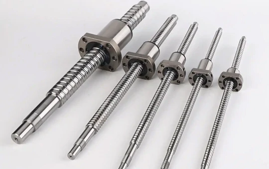
Ball Screw Machining: Complete Guide to Process, End Machining & Hard Turning
What is ball screw machining?
How to manufacture ball screw by machining?
Ball screw machining is a subtractive process that removes material to achieve precision geometries, distinguishing it from turning (sometimes considered additive). Precision-machined ball screws minimize backlash and improve positional accuracy over conventional leadscrews. Beyond fasteners, they serve as linear rails in machine slides, delivering rigidity, accuracy, and efficient motion control. Ball screw machining requires sequential operations: bearing hole, keyway, end threading, taper hole; rack groove; nut groove; nut slot and groove; and through holes for internal threading.
What Are the Critical First Steps Before Machining?
Before the first chip is ever cut, successful ball screw machining depends entirely on three critical preparatory steps. First, you must thoroughly interpret the bearing support drawing to capture every tolerance and dimension. Second, select the optimal raw ball screw stock based on project-specific requirements. Third, execute a rigorous pre-machining inspection to catch hidden defects. Overlooking any of these steps invites costly scrap, rework, and lost machine time.
Decode the Bearing Support Drawing
Think of the bearing support drawing as your roadmap to a perfectly machined component. Every number and symbol dictates where and how precisely you must cut. Focus on these four critical data points:
| Feature | Why It’s Critical |
| Journal Diameters | Often specified with a tolerance class like h6. Too loose causes vibration; too tight risks bearing damage during assembly. |
| Shoulder Locations | Act as hard stops for bearings. Their exact spacing controls bearing preload, directly influencing machine rigidity and accuracy. |
| Thread Specifications | Locknut threads must be exact—this is what secures the entire bearing assembly. |
| Overall Length | The final machined length; always verify before you face the end. |
A single misinterpretation here creates a ripple effect of misalignment, ultimately degrading machine performance. Measure twice, cut once starts on paper.
Perform a Pre-Machining Inspection
Even with perfect drawings and premium stock, hidden defects can sabotage hours of work. This three point inspection is your final chance to catch problems before machining begins:
- Shipping Damage Scan— Inspect every thread for nicks, dings, or dents. A damaged raceway will jam the ball nut or cause premature wear.
- Straightness Verification— Place the screw on a granite inspection table and roll it against a dial indicator. Even 0.001″ runout creates vibration and positional errors in the finished assembly.
- Ball Nut Travel Test— Handslide the nut from end to end. Any tight spot or binding signals a screw or nut defect. Discover it now, not after you’ve machined the ends.
How Should You Securely Clamp a Hardened Ball Screw?
How do you securely clamp a hardened ball screw in a powerful lathe without crushing its precision ground raceway? The answer is simple: never allow standard chuck jaws to touch the threads directly. Instead, deploy a protective split bushing or collet system to distribute clamping force evenly, then validate with a dial indicator until runout measures below 0.0005″ (0.012 mm) . Skip this protocol, and you will scrap an expensive component before the first chip is cut.
Why Standard Chuck Jaws Fail
Using standard serrated steel jaws directly on a ball screw thread is catastrophic.
- It destroys the raceway.The “thread” is actually a precision ground track for ball bearings. Sharp jaws bite in, creating permanent dents that cause rough motion, vibration, and premature wear when the ball nut travels over the damage.
- It provides a poor grip.Jaws contact only the thread crests, offering minimal surface area. This weak hold invites vibration or slippage—making accurate machining impossible.
- It creates stress risers.Concentrated pressure at tiny contact points induces micro cracks in hardened steel, which can propagate and cause screwend failure under load.
The Professional Solution: Protective Clamping
Eliminate direct jaw contact with a sacrificial barrier. Two methods dominate precision shops:
- Split Bushing— A custom sleeve (aluminum or brass) is bored to match the thread OD, split lengthwise, and clamped around the screw. Chuck jaws grip the bushing O.D., distributing force 360° evenly. This is the most accessible method for job shops and oneoffs.
- Collet System— A tapered collet tightens uniformly around the workpiece when drawn into the spindle. It provides superior concentricity and rigidity with full 360° contact—the gold standard for highprecision or repetitive production.
Both methods completely protect the raceway while delivering the gripping power needed for aggressive hard turning with CBN tooling.
Final Alignment: Zero Runout Is Non-Negotiable
Clamping alone isn’t enough. Any runout will be machined directly into your bearing journals, ruining concentricity with the screw axis. Follow this proven sequence:
- Mount a dial indicatoron a magnetic base, stylus touching the screw O.D. near the chuck.
- Rotate the chuck by handone full revolution. Watch the needle—any movement indicates runout.
- Adjust for zero runout.Gently tap the screw within the bushing or collet until needle movement is <0.0005″ (0.012 mm) . Patience here pays.
- Support the opposite endwith a live center in the tailstock to prevent whipping and vibration.
Which Tools and Machine Settings Are Required for Hard Turning?
Machining a hardened ball screw—typically heat treated to 58–64 HRC on the Rockwell C scale—demands far more than standard tooling. You need a specific combination of ultra hard tool materials and precisely calculated machine parameters to cut steel that’s as tough as a file. This process is called hard turning, and it simply will not succeed with conventional carbide inserts.
Your single most important decision? Choosing the right cutting tool insert.
| Tool Material | Best For | Performance on Hardened Steel (58+ HRC) | Why It Works (or Fails) |
| Carbide | General machining of soft steels, aluminum, plastics | Fails immediately. Edge dulls, chips, or breaks within seconds; poor finish and incorrect dimensions. | Carbide cannot withstand the extreme heat and abrasion of hardened steel. The cutting edge softens and deforms. |
| CBN (Cubic Boron Nitride) | Hard turning and abrasive materials | Excellent. Cleanly cuts hardened steel, produces mirrorlike surface finish, holds tight dimensional accuracy. | CBN is the secondhardest material after diamond. It maintains hardness at high temperatures, using the heat to its advantage. |
Why is CBN the only real choice?
Unlike carbide, which melts and deforms, a CBN insert actually leverages the heat generated by high cutting speeds. It softens the steel at the exact point of cut, allowing the tool to shear material away cleanly. For optimal results, select the proper CBN grade and geometry (negative rake angles, specific chip breakers) based on your ball screw material hardness.
Machine Settings: High Speed, Low Feed, Shallow Cut
Even the finest CBN insert will fail without the correct speeds and feeds. For hard turning of ball screws, the governing philosophy is high surface speed, low feed rate, and minimal depth of cut:
| Parameter | Typical Range | Why It Matters |
| Cutting Speed (SFM) | 300–500 SFM | Generates intense, localized heat to soften the steel just ahead of the tool, enabling clean shearing. |
| Feed Rate (IPR) | 0.001–0.003 IPR | Ensures a superb surface finish and avoids excessive tool pressure. You’re skimming, not plowing. |
| Depth of Cut (Finish) | 0.005″–0.010″ | Removes minimal stock to “sneak up” on final dimensions with micronlevel control. |
These are proven starting points, but always verify against your CBN tool manufacturer’s data—machine rigidity and insert grade can shift the ideal window.
Coolant: Not to Cool, But to Control
It sounds counterintuitive: you need heat to cut, but you also need coolant. Here, coolant plays two entirely different roles:
- Chip Evacuation— A high pressure jet blasts razor sharp chips away from the cutting zone. If a hot chip reenters the cut or wraps around the screw, it will instantly ruin your mirror finish.
- Thermal Stability— While the cutting edge runs hot, the entire ball screw must remain at stable temperature. Flood coolant prevents thermal expansion; otherwise, the part will grow during machining and contract afterward, throwing your bearing journal diameters out of tolerance.
The goal? Keep the workpiece cool while the tool does its hot work at the microlevel. A steady, high pressure stream aimed directly at the tool tip is non-negotiable for achieving submicron accuracy and bearing ready surface finishes.
Ball Screw End Machining: What Are the Types, Advantages, and Critical Best Practices?
Ball Screw End Processing Types
First, you tailor the end geometry to your exact application. Flat machining creates a perfectly flush mounting surface for seamless integration. Keyway machining cuts precision slots for torque transmission keys. Thread machining produces internal or external threads for nuts and accessories. And when standards aren’t enough, customized end machining delivers unique shapes and dimensions engineered specifically for your application.
Advantages You Cannot Ignore
- Improved Connection Accuracy— Think of a precision-machined ball screw end as a tailor-made component for your mechanical system. It docks perfectly with motor shafts, bearings, and transmission devices. The result? Harmonious system operation, dramatically reduced mechanical errors, and immediate gains in overall equipment performance.
- Enhanced Mechanical Strength and Stability— End machining doesn’t just shape metal; it locks in reliability. By engineering the end geometry to fit specific bearings or fixtures, you significantly increase bonding force and system rigidity. More importantly, you eliminate vibration-induced troubles before they start.
- Improved Operational Efficiency— Precision end processing directly reduces friction and wear. That means longer screw life, smoother and faster linear motion, and quicker system response—all translating directly into higher overall efficiency.
- Compatibility and Versatility— Whether through standardized or fully customized solutions, precision end machining enables one ball screw to adapt across diverse applications. From automation equipment to precision machinery to high-end instruments, this flexibility makes it indispensable.
Notes for Zero-Defect Execution
- Tool Selection— Choose cutting tools engineered specifically for hardened steel and your chosen end feature. The right tool is the difference between a mirror finish and a reject tag.
- Cooling and Lubrication— Aggressive coolant application prevents localized overheating, flushes chips cleanly, and preserves both tool life and dimensional stability.
- Precision Control— Every dimension, every tolerance must be strictly controlled in-process. Micron-level errors at the end become catastrophic failures at the assembly stage.
What Is the Correct Sequence for Machining the Ends?
With the hardened ball screw securely clamped and spinning with verified zero runout, and your CBN inserts loaded at the correct speeds and feeds, one critical question remains: in what order do you machine the end features?
The answer is a methodical, four step sequence where each operation builds the foundation for the next. Deviate from this order, and you will lose concentricity, ruin bearing fits, or scrap an expensive component.
| Step | Operation | What You Achieve | Why It’s NonNegotiable |
| 1 | Face & Center Drill | Creates a perfectly flat reference surface and a precision center hole for the live center. | Establishes the zero point for all length dimensions and provides rigid tailstock support to eliminate whipping. |
| 2 | Turn Bearing Journals | Rough and finish turn the precise diameters where support bearings will press fit. | The most critical step. Final diameters often require ±0.0002″ tolerance. A mistake here ruins the entire screw. |
| 3 | Cut Thread Relief & Locknut Threads | Machines a narrow undercut at the journal shoulder, then cuts the locknut threads. | Relief ensures the bearing seats fully flush against the shoulder; accurate threads guarantee secure assembly. |
| 4 | Deburr & Final Quality Check | Removes all razor sharp edges and performs physical test fit with actual bearings and locknut. | Burrs cause scratching, false seating, and lubricant contamination. Test fit proves the job was done right. |
Face and Center Drill — Your Only Foundation
Before any precision feature exists, you must create one. Facing skims the screw end flat and square to the rotational axis. This faced surface becomes your master reference—every length dimension you machine traces back to this zero point.
Immediately after facing, drill a precision center hole exactly on axis. This is not for fastening; it receives the tailstock live center. That single point of support prevents the free end from whipping or vibrating under cutting loads. Without it, submicron accuracy is impossible.
Turn the Bearing Journals — Where Microns Matter Most
The bearing journals are the smooth, precision ground diameters where the support bearings press fit. This is the most demanding operation in the entire sequence.
- Rough turningwith your CBN insert removes bulk stock quickly, leaving 010″–0.015″ for the finish pass.
- Finish turningis a slow, shallow skimming cut at low feed and minimal depth of cut. This pass determines the final diameter and surface finish.
- Constant measurementis mandatory. Stop the lathe, mic the journal, cut a little more, measure again. Repeat until you land inside the print tolerance—often as tight as ±0.0002″.
- Pro tip:Always confirm recommended shaft tolerances directly from the bearing manufacturer’s engineering data. Guessing here guarantees rejection.
Thread Relief and Locknut Threads — Securing the Assembly
With journals finished, you now machine the features that lock everything together.
Thread relief (or undercut) is a narrow groove cut at the base of the journal, where it meets the shoulder. Why? Without it, the journal fillet radius prevents the bearing from seating fully flush. The relief creates clearance so the bearing face contacts the shoulder solidly—essential for proper preload and load distribution.
Next, cut the locknut threads to print (e.g., M20 x 1.0). Use a dedicated threading tool and verify fit with a thread gauge. The locknut must spin on smoothly—no binding, no slop.
Deburr and Final Quality Check — Proof of Perfection
Machining is complete, but the job is not finished.
Deburring is the delicate manual removal of every microscopic, razorsharp edge left by cutting tools. A fine file or specialized deburring tool does the work. Burrs are not just cosmetic flaws—they act like tiny knives, scratching mating components, preventing bearings from seating, or breaking off during operation to contaminate lubricant and destroy the ball nut.
Finally, the ultimate test: slide the actual bearing onto the journal and thread on the locknut. You are not just measuring—you are feeling the fit. It should be smooth, snug, and absolutely free of play.
This physical confirmation is the only true proof that every previous step was executed correctly.
What Are the Key Applications and Manufacturing Challenges of Modern Ball Screws?
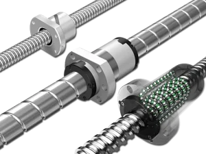
Screw nut unit
The screw nut unit stands as a high efficiency actuator, expertly converting rotational motion into smooth, reliable linear motion. Broadly speaking, two structural architectures exist: the traditional split nut and the increasingly dominant integral nut. However, the integral nut delivers decisive advantages that are redefining modern motion control.
First, it integrates a four point angular contact ball bearing directly into the nut body—creating a dramatically more compact structure without compromising load capacity. Second, by eliminating the inner bearing ring, engineers can deploy larger diameter steel balls, which directly increases load bearing capacity and enables reliable high torque transmission. Third, this intelligent integration reduces the total part count and simplifies system assembly, accelerating production cycles while elevating overall quality. Finally, because the ball bearing and nut share a unified coaxial design, you gain superior coaxiality—translating directly into silky smooth operation, lower noise, and measurably better NVH performance.
As a direct result of these performance breakthroughs, ball screws powered by advanced screw nut units have become indispensable across the automotive industry—especially as electrification accelerates. Today, they are engineered into the core subsystems of new energy vehicles: steering systems, braking systems, parking systems, and suspension systems, where micron level precision, zero compromise efficiency, and long term reliability are simply non-negotiable.
Electric Power Steering (EPS)
As automotive electronic control systems accelerate toward full integration and intelligence, the caliper integrated electronic parking brake (MOC EPB) is rapidly taking dominance—not only in passenger vehicles but increasingly across light trucks as well.
At the same time, this same demand for precision, reliability, and longterm durability is driving how ball screws are manufactured for CNC machine tools and specialized industrial machinery. In these applications, screw rods must be hardened—typically to 58–65 HRC—to extend service life and maintain micron level accuracy under continuous operation. And once hardened, the screw ends are precision ground using thread grinders to achieve the final geometry and fit.
Screw heat treatment
During heat treatment, bending deformation is a constant threat.
You absolutely must avoid cold straightening. A screw that appears straight after cold working will almost always relapse—bending back days later or, worse, during the grinding process itself.
Only heat straightening is acceptable. It alone preserves long term dimensional stability.
The center hole at both screw ends is not a secondary feature—it is the processing standard from which all accuracy flows.
Always specify a bellshaped center hole. This geometry prevents edge damage that would otherwise compromise the datum.
Hardness here must reach 60–65 HRC—no exceptions.
Screw grinding method and grinding amount selection
Getting grinding parameters right is the dividing line between a high precision ball screw and a rejected one. In fact, correctly selecting the grinding amount directly improves screw accuracy, enhances surface quality, and actively suppresses common defects like ripples and burns that plague hardened components.
So, what goes into the perfect grinding recipe? You must fully account for:
- The workpiece materialand its as heat treated hardness;
- The target surface roughness;
- The grit sizeand hardness grade of your grinding wheel;
- And whether you are in roughingor finishing
But here’s the truth: grinding amount selection does not happen in isolation.
Manufacturing high precision hardened screw rods demands a holistic engineering approach. It begins with intelligent material selection, followed by meticulous orchestration of hot and cold processes to preserve dimensional stability through every thermal cycle. Only then do you deploy precisioncontrolled grinding parameters to lock in final geometry and surface integrity.
Why Choose Колодезный вал? What Does It Deliver?
- Zero compromise precision– Premachined ends, precision centre holes, and verified straightness eliminate clamping damage and runout.
- Hard turning ready– CBN optimized semifinished or fully finished screws cut trial and error, hold ±0.0002″ journals.
- Heat treated stability– Thermal straightening ensures no delayed bending; 58 65 HRC with dimensional integrity.
- Application matched engineering– Tailored for EPS, CNC, EV systems – not just a stock screw, but a validated solution.
FAQs
What is the maximum achievable straightness on a fully heat treated ball screw?
0.02 mm per 1000 mm after thermal straightening and stress relief. Cold straightening is never applied.
Does case depth limit how deeply you can machine the screw ends?
Yes. Case depth is typically 1.5–2.5 mm. Bearing journals and thread reliefs must stay within the hardened layer. Machining below case depth risks core softness and thread stripping.
How is preload consistency maintained across batch production?
By controlling three variables: ball diameter sorting within 0.5 µm, groove lead error below 3 µm per 300 mm, and rigid control of nut ball track position relative to screw axis.
This blog was provided by the Колодезный вал Engineering Team, led by Mr. Xu, Senior Applications Engineer. Welleshaft delivers precisionmachined ball screws with verified straightness, casehardened integrity, and CBNready ends—engineered for aerospace, EV, and medical applications.