
Why Do Robotics Teams Evaluate MIM?
Robotics engineers often focus on compact geometry, precision fit, consistent motion, and stable production. Unlike general industrial components, small tolerance decisions in robotics can directly influence motion accuracy, assembly performance, and long-cycle repeatability.
1.Compact Functional Parts
Joint mechanisms, actuator-linked components, gripper hardware, and feature-dense robot parts are areas where MIM proves valuable for evaluation.
2.Precision Fit Paths
Robotic elements rely on secure mating, smooth motion, and controlled interface alignment—not only on the basic shape. MIM enables tighter fits that support these requirements.
3.Assembly Efficiency
Thoughtfully designed MIM parts simplify compact assemblies and can reduce the need for multiple machining operations in intricate mechanisms.
4.Repeat Production
When robotic parts need frequent repetition, MIM becomes cost-effective, as tooling and process refinement can be justified through consistent high-volume production.
Why Is MIM the Preferred Process for Robotic Components?
Metal Injection Molding (MIM) uniquely combines the design flexibility of plastic injection with the strength of powdered metals. This makes it ideal for robotic parts that must be lightweight, strong, and suitable for high-volume production.
Complex Geometries Without Secondary Machining
Many robotic assemblies, including compact joint components and actuator-linked hardware, feature intricate internal channels, undercuts, and curved surfaces that are difficult and expensive to produce through traditional machining. MIM forms these complex robotic micro components in a single operation, minimizing or eliminating the need for secondary machining. For example, MIM molds and sinters a robotic joint housing that would otherwise require hours of CNC work per part, reducing per-unit costs by 40–60% at volumes above 10,000 pieces while maintaining high dimensional precision.
High Volume Production at Competitive Costs
Robotics programs often demand repeatable components at scale. When high-quantity custom parts exceed production runs of 5,000 units, MIM delivers cost efficiency that rivals CNC machining or investment casting. The upfront tooling investment is quickly offset by savings during repeat production.
Excellent Material Properties
Sintered MIM parts achieve 95–99% of theoretical density, offering mechanical performance comparable to wrought metal. For robotics, this ensures that precision-fit components, motion-sensitive hardware, and other repeat-use contact hardware can endure repeated stress cycles, impact loads, and thermal variation typical in automated systems.
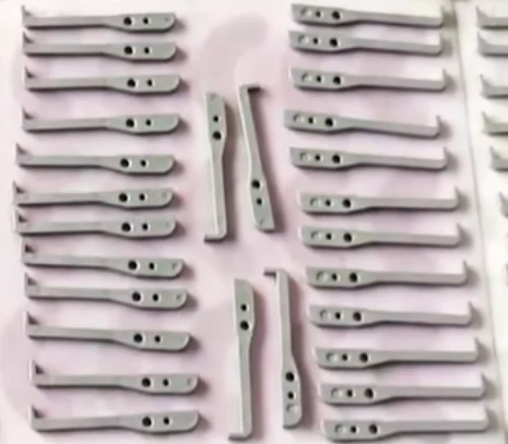
What Robotics Components Are Best Suited for MIM Production?
Robotics applications usually group parts by function rather than by appearance, because performance depends on how each element supports motion, alignment, and load transfer. In most evaluations of MIM, the focus is on whether each component can maintain stability under repeated movement, tight tolerances, and compact assembly constraints.
Joint and Motion Details
- Compact joint components
- Motion-transfer details
- Small pivot hardware
- Feature-dense mechanism parts
In robotic motion systems, joint areas are typically where load, rotation, and alignment all intersect. These compact joint components and small pivot hardware require consistent geometry to prevent drift or backlash during continuous operation. Engineers often assess complex robotic micro components to determine whether they can maintain stability under repeated cycles without additional machining.
Gripper and End-Effector Parts
- Finger-related mechanism details
- Compact retention components
- Precision small interfaces
- Repeat-use contact hardware
End-effectors depend heavily on accuracy at the contact point. Finger-related mechanism details and repeat-use contact hardware are usually reviewed for wear resistance and motion repeatability. At the same time, precision small interfaces must maintain alignment so gripping force remains consistent over time.
Actuator-Linked Components
- Small lever and drive details
- Compact support parts
- Miniature mechanical interfaces
- Movement-sensitive hardware
Actuation systems rely on smooth force transmission through small structural elements. Small lever and drive details and movement-sensitive hardware are typically evaluated for fatigue resistance and response stability. These miniature mechanical interfaces must also support tight assembly conditions without deformation under load.
Sensor and Module Housings
- Small protective housings
- Feature-dense support parts
- Compact mounting details
- Geometry-driven metal elements
Sensor protection is not only about shielding electronics but also about maintaining positional accuracy. Small protective housings and compact mounting details are often designed to keep sensors aligned even under vibration. Geometry-driven metal elements help integrate structural rigidity with functional layout in confined spaces.
Transmission and Control Details
- Small gear-adjacent parts
- Locking and indexing details
- Precision-fit components
- Repeat-motion interfaces
Transmission modules require consistent engagement between moving parts.Engineers typically assess precision-fit components and locking or indexing details to determine how well they maintain synchronization. They focus on repeat-motion interfaces, especially in systems where timing accuracy directly impacts robotic performance.
Custom Robotics Mechanism Parts
- Compact working components
- Fit-sensitive metal details
- Assembly simplification opportunities
- High-quantity custom parts
Custom robotic structures often combine multiple functions into a single geometry.Engineers evaluate fit-sensitive metal details for dimensional stability and consider assembly simplification opportunities to reduce multi-part builds.High-quantity custom parts make process consistency a key factor in MIM suitability.
Gearbox and Transmission Parts
Precision gears remain one of the most critical elements in robotic systems. MIM supports the production of spur gears, planetary gears, and worm gears with controlled tooth geometry and consistent surface finish.
Common material choices include 17-4PH stainless steel for corrosion resistance and Fe-2Ni steel for cost-efficient strength performance. With typical tolerances around ±0.3%, these parts are suitable for stable torque transfer in robotic actuators and gearbox assemblies.
Sensor Housings and Mounting Brackets
Robotic sensing systems require housings that protect internal electronics while preserving alignment accuracy. MIM enables integration of mounting features, sealing surfaces, and cable routing into a single structure.
Engineers commonly select materials such as 316L stainless steel and 17-4PH stainless steel for their corrosion resistance and mechanical stability, especially in long-term operating environments.
Joint Connectors and Structural Components
Robot joints are exposed to complex multi-directional loads during movement. Joint connectors and structural brackets produced via MIM help maintain strength while keeping weight under control.
Thin-wall capability and uniform density reduce weak points that may appear in machined or cast alternatives, improving reliability under continuous motion cycles.
End Effector Components
Grippers, tool changers, and related modules require a balance of precision, durability, and lightweight structure. MIM supports complex geometries such as gripper fingers, quick-change adapters, and functional inserts that would otherwise require multiple machining steps.
Component Overview (Robotics MIM Applications)
| Component Type | Typical Material | Key MIM Advantage | Volume Range |
| Gears and Pinions | 17-4PH / Fe-2Ni | Tooth accuracy, no post-machining | 10,000+ |
| Sensor Housings | 316L Stainless | Integrated structure, corrosion resistance | 5,000+ |
| Joint Connectors | 17-4PH / Titanium | High-strength complex geometry | 5,000+ |
| Gripper Fingers | 17-4PH / MIM Steel | Wear resistance, lightweight design | 10,000+ |
| Mounting Brackets | Fe-2Ni / 316L | Cost efficiency at scale | 10,000+ |
| Heat Sinks | Copper / Aluminum alloys | Thermal + complex fin structures | 5,000+ |
Why Is MIM in Collaborative Robots (Cobots) a Growing Opportunity?
Collaborative robots, or cobots, are becoming one of the fastest-expanding areas in automation. Unlike traditional industrial robots that operate in isolated environments, cobots are designed to work directly alongside human operators. This creates stricter requirements for safety, compactness, and structural reliability in every mechanical element.
Why MIM fits cobot design requirements
In cobot systems, space is limited and every gram matters. MIM supports the development of lightweight robotic components that still maintain high structural strength. This balance is essential for maintaining safe interaction between humans and machines while keeping overall system size compact.
Typical applications include compact joint components, force-torque sensor housings, and safety-rated structural brackets. These functional micro-mechanical parts are often selected because they require both precise geometry and consistent mechanical behavior in repetitive motion environments.
Growth-driven demand for precision metal parts
The cobot sector continues to expand rapidly, with demand expected to grow at over 30% CAGR through 2028. As production scales, the need for high-quantity custom parts increases significantly, especially for standardized yet precision-driven components.
This growth directly benefits MIM parts, since the process is well suited for repeat production, stable dimensional control, and complex geometries that are difficult to achieve through conventional machining.
What Makes Humanoid Robots the Next Frontier for MIM Technology?
Humanoid robots are emerging as one of the most advanced directions in robotics development, and they create a new level of demand for precision mechanical design. A single humanoid system can integrate hundreds of metal components, ranging from finger articulation structures to wrist actuation systems and hip or spine support assemblies.
Rising part complexity drives demand for MIM
Each humanoid robot typically contains around 200–500 precision metal parts, many of which fall into categories such as compact joint components, actuator-linked components, and precision small interfaces. These feature-dense mechanism parts require tight dimensional control, consistent motion behavior, and repeatable manufacturing quality.
With global investment in humanoid robotics exceeding billions annually and production scaling quickly in major manufacturing regions, demand for high-quantity custom parts continues to rise, especially for geometrically complex components that are difficult to machine economically.
Material requirements for humanoid robot structures
Humanoid systems require materials that balance strength, weight, and long-term durability under continuous movement. In many designs, MIM parts are selected because they can achieve both structural integrity and complex shaping in a single process.
- Titanium MIM components are often used in load-bearing joints where strength-to-weight performance is critical.
- Stainless steel MIM partsare commonly applied in exposed or wear-sensitive areas due to their corrosion resistance.
- Soft magnetic MIM materialsare increasingly used in electromagnetic actuator systems, where efficient response depends on controlled magnetic properties and stable performance in motion-sensitive hardware.
As humanoid robotics continues to expand, the need for compact, repeatable, and high-precision metal solutions positions MIM as a key enabling manufacturing process for next-generation robotic architectures.
What Are the Key Design Considerations for MIM Robotics Parts?
When developing robotic components for MIM, careful design planning is essential to ensure both manufacturability and functional performance. Attention to geometry, material, and dimensional control can significantly impact precision-fit components and functional micro-mechanical parts.
Wall Thickness Uniformity
Maintaining consistent wall thickness, generally between 1.5–6 mm, helps control shrinkage behavior during sintering and reduces the risk of distortion. Engineers avoid abrupt changes in thickness in compact joint components, housings, and structural brackets to preserve dimensional stability and repeat-motion interface accuracy.
Tolerance Specifications
Typical MIM tolerances of ±0.3% of nominal dimension are achievable without additional processing.Engineers achieve tighter tolerances of around ±0.1–0.2% in movement-critical zones and fit-sensitive metal details by applying selective secondary operations such as machining, coining, or sizing. This approach ensures reliable assembly performance in robotic systems.
Material Selection Strategy
Material choice depends on the operational demands of each component. For high-stress load-bearing joints, 17-4PH stainless steel or titanium MIM parts provide exceptional strength-to-weight performance. For components exposed to corrosive environments, 316L stainless steel is preferred. The material selection also affects wear resistance, post-processing requirements, and the durability of repeat-use contact hardware.
This design approach ensures that compact robotic components produced via MIM meet stringent functional, dimensional, and production-volume requirements.
What Usually Decides Success in Robotics MIM?
In robotics-focused applications, success in MIM is rarely determined by shape alone. What matters more is how geometry, motion behavior, material choice, and production logic interact under real operating conditions. Small oversights in early design review can easily lead to performance issues later in assembly or long-term use.
Main Risk Signals to Review Early
Functional features concentrated in a very small part
When compact robotics components include too many features in a tight area, the design may appear feasible but becomes difficult during molding and shrink control. High local feature density often increases variation risk and makes inspection more complex, even if the overall shape looks stable.
Motion path not reviewed with material and surface choice
In many cases, motion-transfer details and wear behavior are defined too late in the development stage. A part may pass dimensional checks, but without considering surface finish and material pairing, repeat-motion interfaces can degrade faster than expected during real operation.
Fit-critical interfaces treated like general dimensions
Areas such as assembly holes, contact faces, and precision-fit components require tighter tolerance thinking than standard geometry. If these fit-sensitive metal details are treated as general dimensions, small deviations can accumulate and affect overall robotic movement accuracy.
Very low-volume part forced into a tooling-heavy route
Even if a design is technically suitable for MIM, low production demand can create cost imbalance. High-quantity custom parts benefit most from MIM economics, while low-volume cases may not justify tooling investment over the product lifecycle.
Secondary operations ignored during part evaluation
Successful robotic components often rely on post-processing steps such as machining, polishing, or sizing. Ignoring these assembly simplification opportunities can lead to unrealistic expectations about final tolerances and functional stability.
Two realistic engineering examples
A common robotics MIM challenge appears in compact joint or gripper structures where feature-dense mechanism parts sit close to thin supporting wallsAlthough engineers can manufacture the part, controlling shrinkage and achieving final alignment becomes difficult if they do not properly separate working features from non-functional geometry.
Another frequent sourcing issue occurs when engineers evaluate MIM parts solely based on machining cost.Without considering motion-sensitive hardware, secondary operations, assembly logic, and long-term production volume together, the comparison often leads to incomplete decision-making.
What Do Robotics Buyers Usually Look for Beyond Basic Manufacturability?
In evaluating MIM for robotics, buyers focus on more than just whether a part can be molded. They are concerned with how the design will perform under real operating conditions, including motion reliability, assembly accuracy, and long-term stability.
Working Surface Definition
Designers clearly define contact zones, fit surfaces, and movement-critical areas early in the design stage. By identifying these precision small interfaces, they assess the part based on functional performance rather than simple geometry.
Assembly Fit Logic
Before releasing tooling, engineers treat assembly holes, mating faces, and movement-related interfaces separately from general dimensions. This approach ensures that fit-sensitive metal details remain intact and that compact assemblies align correctly without requiring additional adjustments.
Surface and Post-Process Planning
For repeat-use contact hardware and other high-precision components, surface treatment plays a crucial role. Polishing, coating, passivation, or selecting the proper base material directly influence long-term wear, motion smoothness, and repeat-motion interface reliability.
Repeat Production Stability
Robotics programs rely on consistent performance across multiple runs. Buyers often look for high-quantity custom parts that maintain dimensional accuracy, functional fit, and mechanical reliability throughout the production lifecycle, not just in the initial samples.
What Are the Challenges and Solutions in MIM for Robotics?
Producing robotic components via MIM involves unique challenges due to the combination of complex geometries, high-performance requirements, and rapid development cycles. Addressing these issues ensures precision-fit components, compact joint components, and other feature-dense mechanism parts meet both design and production goals.
Meeting Tight Delivery Timelines
Robotics development cycles are often shorter than traditional manufacturing sectors. To keep pace, MIM suppliers need to provide rapid prototyping and fast tooling solutions. Advanced approaches now allow lead times of 4–6 weeks, compared to 8–12 weeks in conventional tooling, enabling faster time-to-market for high-quantity custom parts such as sensor housings and actuator-linked components.
Quality Assurance for Safety-Critical Applications
Many robotic components—particularly in collaborative robots and humanoid robots—are safety-critical. Quality management must extend beyond standard checks to include 100% dimensional inspection of movement-critical zones, statistical process control (SPC), and full material traceability.
While certifications like ISO 9001 and IATF 16949 provide a baseline, robotics components often require compliance with functional safety standards such as ISO 13849 to ensure consistent performance in human-interactive environments.
Scaling from Prototype to Mass Production
Transitioning from small-scale prototypes to repeat-production robotics components is a key challenge. MIM manufacturers with scalable capabilities bridge this gap through pilot production runs, phased tooling investments, and structured production ramp-up. This ensures compact joint components, precision small interfaces, and repeat-use contact hardware maintain both dimensional fidelity and functional reliability across large-volume orders.
How Can Robotics Pages Be Structured From Part Review to Production Logic?
In robotics-focused MIM applications, the evaluation flow is usually structured around how a part moves from concept to stable production. Instead of looking at geometry alone, the focus shifts toward performance behavior, manufacturability boundaries, and repeat production consistency.
Part Screening
At the earliest stage, engineers review feature-dense mechanism parts for geometry complexity, expected service life, and whether MIM is genuinely more suitable than machining or alternative processes. This step prevents over-engineering or misaligned process selection.
Material Review
Engineers evaluate material selection not only for strength but also for motion compatibility. Engineers evaluate motion-sensitive hardware, wear behavior, and surface interaction to determine whether the chosen alloy supports long-term repeat-motion interfaces and requires post-processing to achieve final performance targets.
Tolerance Split
Engineers separate what they can achieve through molding and sintering from what they must control later.Precision-fit components often require this split, ensuring that critical functional zones are not over-reliant on post-machining while still maintaining dimensional control where needed.
Working Feature Planning
Engineers organize designs by function, separating general structure from movement-critical hardware and fit-sensitive metal details. This approach reduces risk during production and helps maintain stable behavior in compact robotic assemblies.
Production Preparation
Engineers align tooling strategy, inspection planning, and post-process routes with expected demand before release. For high-quantity custom parts, this ensures that production stability, quality consistency, and assembly performance remain controlled across multiple batches.
How Does Welleshaft Support Robotics with MIM?
Metal Injection Molding (MIM) is transforming the production of robotic components, from industrial gearboxes to humanoid joint assemblies, by delivering precision, complex geometry, and scalable production.
Welleshaft specializes in providing robotics manufacturers with end-to-end MIM solutions. Our capabilities include:
- Engineering Design Support– optimizing compact joint components and functional micro-mechanical parts for manufacturability and functional performance.
- Quality Assurance– implementing strict inspection protocols and tolerance control for precision-fit components and repeat-motion interfaces.
- Scalable Production– supporting both prototypes and high-quantity custom parts to meet rapid production cycles without compromising consistency.
- Material Expertise– selecting and processing alloys like 17-4PH stainless steel, titanium, and 316L stainless steel to achieve strength, corrosion resistance, and reliability.
By partnering with Welleshaft, robotics companies gain a competitive edge through faster time-to-market, enhanced component performance, and reliable repeat production stability—making MIM the process of choice for the next generation of robotic systems.
What Are the Most Common Questions About Robotics MIM?
What robotics parts are usually good candidates for MIM?
Engineers typically produce parts that perform well in MIM as small, function-driven, and geometrically complex components, especially when they require repeat-volume production. Common examples include compact joint components, gripper hardware, actuator-linked components, sensor housings, and precision small interfaces. These functional micro-mechanical parts benefit most from tight geometry and consistent replication.
Is MIM suitable for all robotics metal components?
Not always. Engineers achieve good results with MIM parts for complex and repeatable geometries, but they produce large or structurally simple components with low production volume more efficiently through machining or casting. They base process selection heavily on part geometry, cost structure, and demand scale.
Why do motion path and wear matter so much for robotics MIM parts?
Robotic systems rely heavily on repeated movement and stable contact behavior. That means motion-sensitive hardware must be evaluated not only by shape, but also by wear resistance and long-term stability. In many cases, material selection and surface treatment are just as critical as the base design of repeat-motion interfaces.
Can robotics MIM parts hold tight working tolerances?
Engineers achieve dimensional control in MIM for robotics by categorizing features. They reliably control some areas through molding and sintering, but they apply a planned tolerance split to precision-fit components. In many cases, they use selective secondary operations to stabilize critical functional zones.
What should be reviewed before tooling is approved for a robotics MIM part?
Before tooling release, multiple factors need to be validated together: geometry feasibility, motion path behavior, wear performance, fit-sensitive metal details, material selection, post-processing requirements, and production volume logic. For high-quantity custom parts, this early review step helps avoid cost and performance issues later in production.
This blog was provided by the Welleshaft Engineering Team. Welleshaft focuses on metal injection molding solutions for precision components, supporting robotics and industrial manufacturers with design, quality control, and scalable production capabilities.