
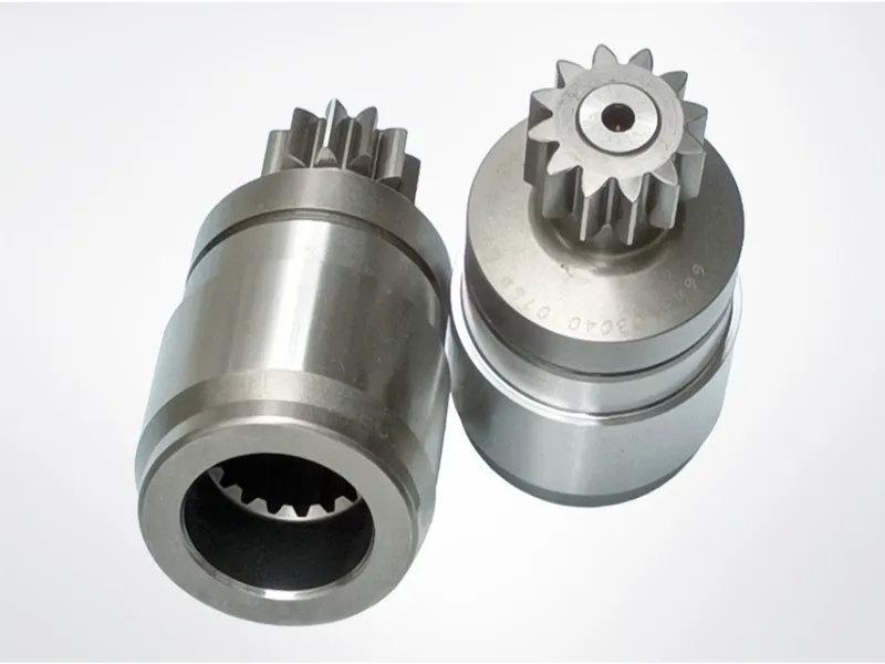
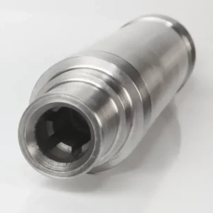
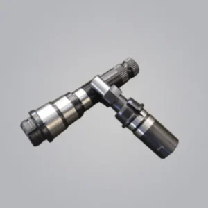
What Is a Pump Shaft in Industrial Pump Systems?
A pump shaft is a mechanical transmission element used inside pumping systems to transfer rotational energy from the driver (such as a motor) to the impeller. During operation, it is continuously subjected to high torque and axial forces, which can lead to stress concentration, bending deformation, fatigue damage, and surface wear if not properly designed.
Because of these demanding working conditions, the pump shaft must combine high mechanical strength with excellent rigidity and dimensional stability. At the same time, resistance to corrosion and abrasion is essential, especially in harsh working environments such as chemical processing, water treatment, agriculture, and industrial fluid transfer systems. Common material selections include stainless steel, duplex stainless steel, and high-strength alloy steels, each chosen based on load capacity and environmental exposure.
From an engineering perspective, a pump shaft is not just a rotating part—it is a core reliability component. It must be precisely designed to handle continuous torque transmission without failure. Any structural weakness or dimensional inaccuracy can lead to system imbalance, unexpected downtime, and costly maintenance, directly affecting overall pump efficiency and operational continuity.
In many modern applications, custom pump shaft manufacturing has become increasingly important. Compared with standard shaft designs, customized solutions provide greater flexibility in material selection, dimensional configuration, and structural features. Through advanced CNC machining processes, shafts can be precisely engineered with keyways, splines, threads, and other coupling interfaces. This level of customization improves compatibility with different pump models and ensures more stable power transmission in specialized operating conditions.
What Is the Relationship Between an Impeller and Pump Shaft?
Have you ever experienced sudden pump inefficiency or complete shutdown without a clear reason? In many cases, the problem is not the entire system but a misunderstanding of its internal components. When key parts are not properly selected or maintained, it often results in performance loss, unexpected failures, and costly downtime.
An impeller and shaft are two fundamental elements in a pump system. The impeller is the rotating component responsible for increasing fluid velocity and pressure, while the shaft acts as the mechanical link that transfers rotational energy from the motor to the impeller, ensuring continuous pumping action.
Understanding the Role of the Impeller
The impeller can be considered the core energy converter within a pump. As it rotates, specially designed blades accelerate the fluid outward, generating pressure through centrifugal motion and enabling continuous flow.
F_c = m,omega^2 r
This principle explains how rotational motion is transformed into fluid movement, forming the foundation of pump operation.
Types of Impellers
Different working conditions require different impeller structures. Selecting the correct type is critical for efficiency and reliability.
| Impeller Type | Best Application | Main Characteristics |
| Closed | Clean liquids | High efficiency, enclosed blades |
| Semi-open | Moderate solids | Balanced clog resistance |
| Open | Slurry fluids | Low clogging risk, easy maintenance |
| Vortex | Fibrous materials | Minimal contact with pumped media |
Each design serves a specific operational environment and directly impacts pump stability.
Material Selection for Impellers
Material choice significantly influences durability and efficiency in what is an impeller and shaft systems.
Common materials include:
- Stainless steel for corrosive environments
- Bronze for marine or seawater applications
- Cast iron for general industrial use
- Polymer composites for cost-sensitive systems
Understanding the Role of the Shaft
The shaft is the transmission backbone of the pump system. Without it, the impeller cannot rotate or generate fluid movement.
Its main functions include:
- Transferring torque from motor to impeller
- Maintaining rotational alignment
- Supporting radial and axial loads
- Ensuring stable and smooth motion
Shaft Design Considerations
Proper engineering of the shaft is essential for long-term reliability in impeller and shaft systems.
Material Selection
- Stainless steel for corrosion resistance
- Alloy steel for wear resistance
- Carbon steel for general-duty applications
Dimensional Design
Key parameters include:
- Length-to-diameter ratio
- Critical speed limitations
- Deflection control under load
Common Shaft Issues and Solutions
Vibration Problems
Uncontrolled vibration is a major failure indicator. It can be reduced through:
- Precision balancing
- Alignment correction
- Routine monitoring
Wear Prevention Strategies
To extend service life:
- Protective sleeves
- Consistent lubrication
- Upgraded material selection
The Impeller–Shaft Connection
The interaction between these two components determines overall pump performance. Even minor connection issues can reduce efficiency or cause premature failure.
Key connection methods include:
- Keyed fits
- Splined connections
- Threaded assemblies
Balance control is equally important:
- Static balancing for stability
- Dynamic balancing for high-speed operation
- Tight assembly tolerance control
Maintenance Best Practices
Regular maintenance is essential for reliable operation of what is an impeller and shaft systems.
Inspection Schedule
- Weekly visual checks
- Monthly performance review
- Quarterly full system inspection
Performance Monitoring
- Flow rate consistency
- Pressure stability
- Vibration trend analysis
Design Considerations for Pump Applications
When designing an impeller and shaft assembly, several operational factors must be evaluated:
Operating Conditions
- Temperature fluctuations
- Chemical exposure levels
- Pressure demands
Performance Targets
- Required flow rate
- Head pressure output
- Energy efficiency goals
Installation Constraints
- Available space
- Maintenance accessibility
- System integration limits
Impact on Pump Efficiency
The coordination between impeller and shaft design directly influences energy consumption and operational cost.
P = rho g Q H
A properly engineered system reduces energy loss and improves hydraulic performance.
Key efficiency factors:
- Optimized component sizing reduces power demand
- Balanced assemblies minimize mechanical losses
- Proper alignment reduces motor overload
What Is the Main Function of a Pump Shaft?
Unexpected pump shutdowns often seem sudden, but in reality they are usually linked to one overlooked mechanical element. When this component underperforms, the entire system can lose stability, resulting in downtime, reduced efficiency, and increased maintenance costs.
The What Is The Main Function Of The Pump Shaft? is to act as the central mechanical link that transfers rotational energy from the motor to the impeller. This energy transfer allows mechanical input to be converted into hydraulic output while maintaining structural balance and load stability inside the pump system.
Core Role: Power Transmission
The most fundamental task of a pump shaft is to transmit torque efficiently. During operation, it must continuously handle rotational force while maintaining structural integrity.
T = F cdot r
This relationship explains how rotational force is generated and transferred through the shaft system.
A well-designed shaft ensures smooth energy transfer from the drive motor to the impeller without unnecessary loss or deformation.
Load-Bearing Responsibilities
Beyond power transfer, the shaft also supports multiple mechanical loads during operation:
- Radial forces generated by impeller rotation
- Axial thrust from internal system pressure
- Weight of rotating assemblies
- Dynamic vibration loads during operation
These combined stresses make the shaft a critical structural component in pump reliability.
Key Design Considerations
Material Selection
Material choice directly affects performance in What Is The Main Function Of The Pump Shaft? applications.
| Type de matériau | Main Advantages | Typical Use Cases |
| Acier inoxydable | Corrosion resistance + strength | Chemical and food systems |
| Acier au carbone | Cost efficiency + general strength | Industrial applications |
| Alloy Steel | High wear resistance | Heavy-duty systems |
| Duplex Steel | Strength + corrosion resistance balance | Marine environments |
Dimensional Design Accuracy
Proper shaft geometry is essential to ensure stable operation and reduce mechanical issues.
Key objectives include:
- Minimizing shaft deflection under load
- Controlling vibration levels
- Ensuring accurate bearing fit
- Maintaining seal performance stability
Operational Performance Factors
Speed and Rotation Stability
Pump shafts must maintain stable performance across varying speeds and load conditions.
Key requirements include:
- Rotational balance control
- Safe critical speed margins
- Reduced vibration levels
- Consistent torque delivery
Environmental Influences
External conditions significantly affect the durability of the shaft system:
- Temperature fluctuations affecting material behavior
- Chemical exposure leading to corrosion risks
- Moisture levels influencing surface degradation
- Particle contamination causing abrasive wear
Manufacturing Precision Impact
High-precision production directly influences how effectively What Is The Main Function Of The Pump Shaft? is achieved in real systems.
Precision Machining Control
Advanced machining ensures:
- Tight dimensional tolerances
- Consistent surface finish quality
- Stable mechanical properties
- Repeatable manufacturing accuracy
Quality Inspection Process
Typical inspection steps include:
- Material certification validation
- Dimensional measurement checks
- Surface roughness evaluation
- Alignment verification
- Dynamic balance testing
Maintenance and Service Life Management
Regular Inspection Focus
To maintain long-term stability, shafts should be regularly checked for:
- Surface wear patterns
- Alignment deviations
- Bearing condition changes
- Seal integrity issues
- Vibration anomalies
Preventive Maintenance Actions
Key practices to extend service life include:
- Scheduled lubrication
- Alignment correction checks
- Continuous vibration monitoring
- Temperature tracking
- Load condition management
System Integration Considerations
Coupling Performance
Proper coupling selection ensures:
- Efficient torque transmission
- Compensation for misalignment
- Vibration reduction
- Easier maintenance procedures
Bearing System Design
Bearing configuration directly affects:
- Load distribution efficiency
- Shaft positional stability
- Operating temperature control
- Overall system reliability
Efficiency and Reliability Factors
Several engineering factors influence overall shaft performance:
- Material mechanical properties
- Surface finishing quality
- Precision alignment
- Dynamic balance accuracy
- Structural optimization design
Improving these aspects enhances both efficiency and durability in pump systems.
Improving System Reliability
To ensure stable operation of systems relying on What Is The Main Function Of The Pump Shaft?, the following aspects are critical:
- Proper dimensional design
- Appropriate material selection
- Precision manufacturing processes
- Correct installation procedures
- Consistent maintenance routines
Why Do Pump Shafts Break During Operation?
Have you ever encountered an unexpected shutdown caused by a damaged pump shaft? The issue goes far beyond a simple mechanical failure—it can disrupt production schedules, increase operational expenses, and create urgent troubleshooting pressure. Once a shaft fails, the entire pumping system may stop functioning, triggering a chain reaction that impacts efficiency and output.
In most cases, a pump shaft failure is not random. It is commonly linked to misalignment, excessive vibration, material fatigue, or insufficient maintenance practices. Identifying these root causes is essential to improve equipment reliability and minimize downtime in industrial environments.
Common Causes of Pump Shaft Failure
Material Fatigue and Stress
One of the most frequent reasons behind pump shaft failure causes is material fatigue. Under continuous cyclic loading, the shaft gradually loses its mechanical strength until failure occurs.
Key contributors include:
- Repeated stress cycles over time
- Harsh environmental exposure
- Fluctuating operating temperatures
- Contact with corrosive chemicals
Even minor stress concentrations can evolve into critical fracture points if left unaddressed.
Misalignment Issues
Pump shaft misalignment remains a leading factor in premature failure. When alignment is not properly maintained, it introduces additional forces that accelerate wear.
| Misalignment Type | Common Symptoms | Potential Consequences |
| Angular | Strong vibration | Early bearing damage |
| Parallel | Abnormal noise | Seal leakage or failure |
| Combined | Temperature increase | Shaft cracking or fracture |
Accurate alignment is essential for maintaining long-term system stability.
Improper Installation and Maintenance
Incorrect setup and poor maintenance routines are often overlooked pump shaft failure causes. Small installation errors can significantly shorten component lifespan.
Critical areas to control include:
- Base and foundation stability
- Coupling alignment precision
- Bearing fitting accuracy
- Lubrication system effectiveness
Impact of Operating Conditions
Speed and Load Variations
Operating conditions directly affect shaft durability. Frequent fluctuations can introduce unexpected stress.
Important factors include:
- Frequent start-stop cycles
- Variable load conditions
- Wide speed operating ranges
- Sudden shutdown events
Environmental Factors
External conditions play a major role in pump shaft durability and long-term performance.
| Environmental Factor | Impact on Shaft | Prevention Measures |
| High humidity | Corrosion | Protective coatings |
| Temperature changes | Thermal stress | Controlled ventilation |
| Chemical exposure | Material degradation | Proper material selection |
| Dust/particles | Surface wear | Sealing systems |
Design Considerations
Material Selection
Choosing the right material is fundamental to reducing pump shaft failure causes.
Important considerations:
- Required mechanical strength
- Resistance to corrosion
- Cost-performance balance
- Material availability
Dimensional Factors
Design accuracy also determines shaft performance and lifespan.
Key parameters include:
- Shaft diameter
- Length-to-diameter ratio
- Critical speed calculations
- Stress concentration zones
Preventive Measures
Regular Inspection Protocols
Routine inspections are essential to detect early signs of pump shaft damage before failure occurs.
Recommended methods:
- Visual condition checks
- Vibration monitoring
- Temperature tracking
- Lubricant analysis
Maintenance Best Practices
| Maintenance Task | Frequency | Purpose |
| Alignment check | Monthly | Avoid misalignment issues |
| Bearing inspection | Quarterly | Identify wear early |
| Lubrication | Weekly | Minimize friction |
| Vibration analysis | Continuous | Detect abnormal behavior |
Modern Monitoring Solutions
Advanced technologies now make it easier to prevent pump shaft failure through predictive insights:
- Real-time vibration monitoring systems
- Integrated temperature sensors
- Digital alignment tools
- Predictive maintenance platforms
What Are the Root Causes of Shaft Failure in Pumps?
In many industrial systems, shaft failures often appear suddenly, bringing production to an unexpected halt. The real issue is that most breakdowns are not caused by a single event but by a gradual accumulation of hidden stresses over time. This makes early detection difficult and recovery expensive.
The root cause of shaft failure is usually a combination of mechanical, operational, and environmental factors. These include misalignment, vibration overload, fatigue accumulation, and inconsistent maintenance practices. Identifying how these factors interact is essential for improving equipment reliability and avoiding repeated failures.
Material Fatigue and Stress Accumulation
One of the most critical contributors to shaft failure root causes is material fatigue. Under continuous cyclic loading conditions, the shaft experiences repeated stress cycles that gradually weaken its internal structure.
sigma = frac{F}{A}
This stress buildup eventually leads to microscopic crack formation, which expands over time until fracture occurs.
Types of Stress Affecting Shaft Performance
- Torsional stress from torque transmission
- Bending stress caused by misalignment
- Axial stress from thrust loads
- Combined stress from multiple operating forces
| Stress Type | Main Source | Effect on Shaft | Prevention Approach |
| Torsional | Power transmission | Twisting deformation | Proper sizing/material use |
| Bending | Misalignment | Surface crack formation | Alignment control |
| Axial | Thrust force | Axial displacement | Thrust bearing support |
| Combined | Multi-load conditions | Complex failure patterns | Full system design review |
Misalignment as a Hidden Failure Trigger
Among all root causes of shaft failure, misalignment is one of the most underestimated factors. Even slight deviations in positioning can significantly increase stress concentration.
Angular Misalignment
- Uneven load distribution across the shaft
- Accelerated bearing wear
- Increased vibration levels
Parallel Misalignment
- Higher radial force loading
- Faster seal degradation
- Excessive heat generation
Combined Misalignment
- Common in real operating systems
- Amplifies multiple stress types
- Requires precision correction methods
Environmental and Operating Influences
External conditions also play a major role in accelerating shaft failure root causes.
Temperature Effects
- Thermal expansion and contraction cycles
- Changes in material mechanical properties
- Reduced lubrication efficiency
Chemical Exposure
- Corrosion development on shaft surfaces
- Progressive material weakening
- Seal compatibility breakdown
Maintenance Gaps and Operational Risks
Poor maintenance is often the indirect driver behind many shaft failures. Without structured inspection routines, early warning signs are easily missed.
Regular Inspection Practices
- Surface condition checks for cracks or wear
- Vibration trend analysis
- Alignment verification procedures
- Bearing condition monitoring
Installation Errors That Lead to Failure
Incorrect installation is another major contributor to what causes shaft failure at the root level.
| Installation Stage | Key Focus | Common Mistake |
| Alignment | Precision positioning | Skipping fine adjustment |
| Mounting | Torque accuracy | Improper tightening |
| Balancing | Dynamic stability | Ignoring minor imbalance |
| Lubrication | Correct application | Wrong quantity/type |
Design Factors Influencing Shaft Reliability
Structural design plays a decisive role in long-term shaft performance.
Material Selection
- Adaptation to operating environment
- Load-bearing capacity evaluation
- Cost vs performance balance
Geometric Optimization
- Reduction of stress concentration zones
- Proper diameter-to-length ratios
- Controlled clearance design
Surface Engineering
- Precision finishing techniques
- Hardening treatment applications
- Protective coating selection
Failure Analysis and Diagnostic Approach
When failure occurs, systematic investigation is necessary to determine the root cause of shaft failure accurately.
Analysis Steps
- Document failure conditions
- Collect operational history
- Identify fracture patterns
- Evaluate material behavior
Common Shaft Failure Patterns
| Failure Pattern | Key Characteristics | Likely Cause |
| Fatigue | Beach mark patterns | Cyclic loading |
| Torsional | 45° fracture lines | Overload conditions |
| Corrosion | Surface pitting | Chemical exposure |
| Wear | Abrasive scoring | Inadequate lubrication |
What Materials Are Best for Pump Shafts in High-Stress Applications?
In demanding industrial environments, pump shafts are constantly exposed to high torque, vibration, pressure fluctuations, and corrosive media. If the wrong material is selected, the result is often premature failure, unexpected shutdowns, and expensive maintenance interventions.
The answer to What Materials Are Best Suited For Pump Shafts In High-Stress Applications? depends on balancing mechanical strength, corrosion resistance, fatigue performance, and long-term cost efficiency. High-performance alloys are typically required to ensure stability under extreme working conditions.
Key Factors in Pump Shaft Material Selection
Before choosing a material, engineers must evaluate multiple performance criteria that directly affect shaft lifespan and reliability.
Core considerations include:
- Resistance to cyclic fatigue loading
- Ability to withstand high mechanical stress
- Corrosion resistance in aggressive environments
- Wear resistance under continuous rotation
- Thermal stability during operation
High-Performance Materials for Pump Shafts
Stainless Steel Grades
Stainless steels are widely used in What Materials Are Best Suited For Pump Shafts In High-Stress Applications? due to their balanced mechanical and chemical properties.
| Grade | Tensile Strength (MPa) | Corrosion Resistance | Cost Level |
| 316L | 485 | Excellent | Medium |
| 17-4 PH | 1070 | Very Good | High |
| 904L | 490 | Superior | Very High |
Duplex Stainless Steels
Duplex grades offer higher strength compared to conventional stainless steels, making them suitable for high-load environments.
| Grade | Avantages clés | Applications typiques |
| 2205 | High strength, chloride resistance | Chemical systems |
| 2507 | Extreme corrosion resistance | Offshore pumping systems |
| S32760 | Excellent pitting resistance | Marine environments |
High-Strength Alloy Steels
For extreme mechanical loads, alloy steels are often preferred due to their superior fatigue resistance and structural strength.
Common characteristics include:
- High load-bearing capacity
- Enhanced wear resistance
- Improved fatigue life under cyclic stress
Material Selection by Application Type
Chemical Processing Systems
In chemically aggressive environments, corrosion resistance is the primary concern.
Typical material choices:
- Super duplex stainless steel
- Hastelloy alloys
- Inconel-based materials
Water Treatment Applications
For water-based systems, cost efficiency and moderate corrosion resistance are key factors.
Common options include:
- 316L stainless steel
- Duplex 2205
- Carbon steel with protective coating
Influence of Operating Conditions
Temperature Effects
Material behavior changes significantly under different temperature ranges, influencing selection in What Materials Are Best Suited For Pump Shafts In High-Stress Applications?
| Temperature Range | Recommended Materials |
| Below 0°C | Low-temperature alloy steels |
| 0–200°C | Standard stainless steels |
| Above 200°C | High-temperature alloys |
Pressure Conditions
High-pressure environments require materials with superior mechanical integrity and fatigue resistance.
Preferred materials include:
- Precipitation-hardened stainless steels
- High-strength alloy steels
- Nickel-based alloys
Wear and Fatigue Considerations
Pump shafts operating under continuous load must resist both abrasive wear and cyclic fatigue damage.
Key performance needs:
- Resistance to surface erosion
- Stability under repeated stress cycles
- Controlled material deformation behavior
Corrosion Resistance Requirements
In harsh chemical or marine environments, corrosion resistance becomes a defining factor in What Materials Are Best Suited For Pump Shafts In High-Stress Applications.
Common solutions include:
- Stainless steel for general corrosion protection
- Inconel for extreme chemical exposure
- Monel for seawater resistance
Manufacturing Considerations
Material selection also directly affects manufacturability and production efficiency.
Important aspects include:
- Machinability of the chosen alloy
- Heat treatment requirements
- Surface finishing capability
- Overall production cost
Machining Complexity Comparison
| Material | Machining Difficulty | Key Requirements |
| 316L | Moderate | Proper cooling and tooling |
| 17-4 PH | High | Precision cutting parameters |
| Duplex | Very High | Rigidity and cooling control |
Cost vs Performance Balance
Material selection is not only a technical decision but also an economic one.
Key cost factors include:
- Initial material price
- Manufacturing complexity
- Expected service life
- Maintenance frequency
- Replacement cycle length
Quality Assurance and Testing
To ensure reliability in What Materials Are Best Suited For Pump Shafts In High-Stress Applications, strict testing is essential:
- Material certification verification
- Non-destructive testing methods
- Dimensional accuracy inspection
- Surface quality evaluation
- Hardness and strength validation
Emerging Material Trends
The industry is evolving toward advanced solutions such as:
- Hybrid composite materials
- Surface-engineered alloys
- Smart materials with monitoring capability
- High-performance corrosion-resistant coatings
Maintenance Implications of Material Choice
The selected material directly influences long-term maintenance strategies:
- Inspection frequency requirements
- Lubrication intervals
- Repair feasibility
- Replacement planning
What Design Features Improve Pump Shaft Durability?
In industrial pumping systems, shaft failure is often not the result of a single defect but a combination of overlooked design weaknesses. Issues such as uneven loading, poor support structure, or insufficient environmental protection can gradually reduce service life and lead to unexpected breakdowns.
The answer to What Design Features Improve Pump Shaft Durability For Industrial Use lies in a well-balanced combination of material engineering, structural optimization, support system design, sealing configuration, and dynamic stability control. These factors collectively determine how well a shaft performs under continuous industrial stress.
Material Selection for Long-Term Durability
Material choice is one of the most influential design decisions affecting shaft lifespan. It determines how the component behaves under load, corrosion, and repeated stress cycles.
Common high-performance options include:
- 316 stainless steel for corrosion-heavy environments
- 17-4 PH steel for high-strength applications
- Duplex stainless steel for combined strength and chemical resistance
Geometric Design and Structural Optimization
Shaft Diameter and Load Handling
Proper shaft sizing is essential for ensuring stable performance in What Design Features Improve Pump Shaft Durability For Industrial Use applications.
This relationship highlights how bending stress is influenced by shaft geometry.
A well-designed diameter must account for:
- Torsional load resistance
- Bending force distribution
- Critical rotational speed limits
- Deflection control under load
| Shaft Diameter (mm) | Load Capacity (kN) | Operating Speed (RPM) |
| 20–30 | 5–15 | 1000–3000 |
| 31–50 | 16–40 | 800–2500 |
| 51–75 | 41–80 | 600–2000 |
Stress Concentration Reduction
Poor geometric transitions often become failure initiation points. To improve durability:
- Smooth diameter transitions are applied
- Optimized fillet radii reduce stress peaks
- Keyway geometry is carefully controlled
- Seal groove design is optimized for load distribution
Bearing System Architecture
A properly designed bearing system ensures shaft stability and reduces mechanical wear.
Bearing Selection Factors
- Load capacity requirements
- Maximum operating speed
- Temperature resistance
- Lubrication compatibility
Bearing Spacing Optimization
Correct spacing helps achieve:
- Reduced shaft deflection
- Lower vibration levels
- Balanced load distribution
- Improved rotational stability
Sealing System Design Integration
Seals play a critical role in protecting internal components and maintaining system efficiency.
Mechanical Seal Design Considerations
- Proper sealing face material pairing
- Controlled spring force distribution
- Optimized flushing arrangements
- Environmental contamination control
Shaft Sleeve Protection
Protective sleeves enhance wear resistance through:
- High surface hardness selection
- Controlled surface finish quality
- Tight clearance tolerance control
- Material compatibility matching
Dynamic Balance and Vibration Control
Maintaining rotational balance is essential for extending shaft service life in What Design Features Improve Pump Shaft Durability For Industrial Use systems.
| Balance Grade | Application Type | Maximum Speed (RPM) |
| G1.0 | Precision pumps | >3000 |
| G2.5 | Industrial systems | 1500–3000 |
| G6.3 | General applications | <1500 |
Vibration Reduction Measures
- Continuous vibration monitoring systems
- Scheduled maintenance inspections
- Precision alignment procedures
- Dynamic balancing corrections
Manufacturing Precision and Quality Control
High manufacturing accuracy is essential for ensuring structural reliability and long service life.
Surface Quality Control
- Controlled grinding processes
- Strict surface roughness limits
- Optimized heat treatment cycles
- Multi-stage inspection procedures
Dimensional Accuracy Requirements
- Concentricity control
- Roundness precision
- Straightness tolerance
- Run-out limitation
Environmental Protection Design Features
Corrosion Resistance Strategies
To improve durability in harsh environments:
- Protective coating applications
- Environment-specific material selection
- Optional cathodic protection systems
- Scheduled surface maintenance
Thermal Management Design
Temperature control is critical for long-term stability:
- Integrated cooling system design
- Efficient heat dissipation structures
- Real-time temperature monitoring
- Thermal expansion compensation features
Maintenance-Oriented Design Features
Modern shaft designs also consider ease of maintenance to reduce downtime.
Accessibility Improvements
- Removable coupling guards
- Easily accessible lubrication points
- Modular assembly structure
- Clear maintenance reference markings
Monitoring Integration
- Vibration sensor mounting points
- Temperature measurement interfaces
- Pressure monitoring ports
- Alignment inspection features
Design Impact on Long-Term Performance
Well-engineered shaft systems significantly improve operational stability and reduce failure risk. When What Design Features Improve Pump Shaft Durability For Industrial Use? principles are properly applied, the result is:
- Extended service life
- Reduced maintenance frequency
- Improved operational efficiency
- Lower lifecycle cost
How Can CNC-Machined Pump Shafts Prevent Premature Wear?
In industrial pumping systems, one of the most common long-term issues is unexpected surface degradation of shafts. What makes it more problematic is that this wear does not happen suddenly—it gradually develops until performance drops or failure occurs, often without early warning.
The How To Prevent Premature Wear In CNC-Machined Pump Shafts,approach focuses on controlling the main contributing factors such as material quality, machining precision, surface condition, alignment accuracy, and operating environment. When these elements are properly managed, shaft lifespan can be significantly extended.
Material Selection and Performance Stability
The foundation of wear resistance begins with selecting the correct base material. In CNC machining applications, material behavior under load and friction is a key factor in long-term durability.
Different materials respond differently to stress, corrosion, and repeated motion. Choosing the wrong one often leads to accelerated degradation.
| Material | Avantages clés | Applications typiques |
| 316 Stainless | Corrosion resistance + stability | Chemical pump systems |
| 17-4 PH Steel | High hardness + strength | High-pressure environments |
| Duplex Steel | Strong corrosion resistance | Marine and offshore systems |
| Acier au carbone | Cost efficiency + machinability | General pumping applications |
Surface Quality in CNC Machining
Precision surface finishing plays a major role in reducing friction-related wear in How To Prevent Premature Wear In CNC-Machined Pump Shafts processes.
Ra < 0.4,mu m
Lower surface roughness reduces friction contact between components and improves lubrication stability.
Critical Surface Requirements
- Controlled surface roughness below industrial limits
- Accurate cylindricity and roundness control
- Uniform machining texture distribution
- Reduced micro-defect formation
Alignment and Assembly Precision
Even a perfectly machined shaft can wear prematurely if installation alignment is inaccurate. Misalignment introduces uneven load distribution and increases friction zones.
Common Alignment Techniques
- Laser-based alignment systems
- Dial indicator measurement methods
- Digital shaft alignment tools
- Scheduled recalibration checks
Lubrication System Optimization
Lubrication is one of the most effective ways to reduce wear in CNC-machined shafts. It creates a protective film that minimizes direct metal contact.
Key lubrication control strategies:
| Strategy | Function | Implementation Method |
| Oil Analysis | Detect wear particles | Scheduled sampling |
| Film Control | Maintain lubrication layer | Proper oil selection |
| Flow Regulation | Ensure even distribution | System design optimization |
| Thermal Control | Maintain viscosity stability | Cooling integration |
Environmental Protection Strategies
External conditions significantly influence wear rate in How To Prevent Premature Wear In CNC-Machined Pump Shafts applications.
Key protection methods include:
- Sealed bearing systems to block contaminants
- Protective surface coatings to resist corrosion
- Environmental shielding structures
- Routine cleaning and contamination control
Manufacturing Precision and Quality Control
High-quality CNC machining directly impacts shaft durability. Precision manufacturing ensures tight tolerances and consistent geometry across components.
Key Inspection Areas
- Dimensional accuracy verification
- Material certification validation
- Surface finish measurement
- Hardness consistency checks
- Concentricity and roundness inspection
Load Management and Operating Control
Improper loading conditions often accelerate shaft degradation. Managing operational stress is essential for extending service life.
Key control strategies include:
- Operating within design load limits
- Monitoring system pressure variations
- Controlled startup and shutdown procedures
- Managing thermal expansion effects
Design Optimization for Wear Reduction
Engineering design has a direct influence on long-term wear resistance in CNC-machined pump shafts.
Critical design improvements include:
- Optimized shaft diameter for load balance
- Reduction of stress concentration zones
- Proper bearing spacing design
- Smooth material transition areas
Advanced Monitoring Systems
Modern predictive technologies help detect early wear signs before failure occurs.
Common monitoring methods:
- Vibration pattern analysis
- Temperature tracking systems
- Oil particle contamination detection
- Performance trend evaluation
Implementation Strategy for Wear Prevention
To effectively apply How To Prevent Premature Wear In CNC-Machined Pump Shafts a structured approach is required:
- Establish baseline operating conditions
- Train maintenance and operation personnel
- Implement continuous monitoring systems
- Define corrective action procedures
- Regularly review and optimize maintenance strategies
How Is a Pump Shaft Measured for Precision Engineering?
Accurate dimensional checking of a pump shaft is often more complex than it appears. Even small measurement errors can lead to poor assembly fit, vibration issues, or premature equipment failure. In industrial applications, precision is not optional—it directly determines pump reliability and service life.
To correctly understand how to measure a pump shaft, it is essential to use high-precision instruments and follow a structured measurement process. Key parameters such as diameter, length, straightness, and runout must all be evaluated carefully using repeatable methods.
Essential Tools for Shaft Measurement
Accurate inspection begins with the right equipment. Without proper tools, measurement results can easily become inconsistent.
Primary Instruments
- High-precision micrometers
- Digital calipers (0–300 mm range)
- Dial indicators with magnetic base
- V-block support fixtures
- Surface reference plates
- Roundness measurement devices
Supporting Tools
- Cleaning and degreasing materials
- Calibration reference standards
- Environmental control instruments
- Standardized inspection sheets
Key Measurement Parameters in Pump Shafts
Understanding how to measure a pump shaft requires focusing on several critical geometric features.
Diameter Measurement
Shaft diameter determines proper fitting with bearings, seals, and couplings. Even slight deviations can cause serious assembly issues.
Recommended procedure:
- Clean the shaft surface thoroughly
- Use calibrated micrometers for accuracy
- Measure at multiple axial positions
- Record readings at different angular points (0°, 45°, 90°, 135°)
| Measurement Area | Tolerance Range (mm) | Sampling Positions |
| Bearing Journal | ±0.013 | 4 positions |
| Seal Section | ±0.025 | Minimum 3 points |
| Coupling Zone | ±0.013 | 4 positions |
Length Measurement
Accurate length control ensures correct pump assembly alignment.
Key steps include:
- Measuring overall shaft length with digital calipers
- Checking sectional lengths individually
- Verifying shoulder-to-shoulder distances
- Confirming keyway alignment positions
Advanced Shaft Measurement Techniques
Runout Inspection
Runout measurement is critical when evaluating rotational stability in how to measure a pump shaft processes.
Procedure:
- Mount shaft between centers
- Position dial indicator correctly
- Rotate shaft slowly and steadily
- Record deviation at 45° intervals
| Runout Type | Max Allowable (mm) | Measurement Method |
| Total Runout | 0.05 | Full rotation scan |
| Bearing Section | 0.025 | Multiple points |
| Seal Section | 0.038 | Minimum 3 readings |
Straightness Evaluation
Straightness directly affects vibration behavior and long-term pump stability.
Typical method includes:
- Supporting shaft on precision V-blocks
- Using dial indicators along full length
- Measuring deviation at fixed intervals
- Recording deflection trends systematically
Quality Control Factors
Temperature Influence
Thermal conditions can significantly distort measurement accuracy. Even minor temperature differences may cause dimensional variation.
Best practices:
- Maintain stable room temperature
- Allow shaft to acclimatize before inspection
- Apply temperature compensation when needed
- Record environmental conditions during measurement
Documentation and Traceability
Proper recordkeeping is essential in how to measure a pump shaft workflows to ensure repeatability and traceability.
Required records include:
- All measured values
- Calibration certificates
- Environmental conditions
- Digital inspection logs
Common Measurement Problems and Solutions
Sources of Error
Measurement inaccuracies often arise from:
- Improper tool calibration
- Operator inconsistency
- Environmental instability
- Surface contamination
Corrective Actions
To improve reliability:
- Regular calibration of instruments
- Standardized operator training
- Controlled inspection environment
- Strict surface cleaning procedures
Best Practices for Accurate Shaft Measurement
Consistent results depend on disciplined measurement procedures.
Key practices include:
- Always use calibrated instruments
- Follow standardized measurement steps
- Maintain a controlled inspection environment
- Double-check critical dimensions
- Record all data systematically
Relevant Industry Standards
| Standard | Application Area | Key Focus |
| ISO 1101 | Geometric tolerancing | Form and position rules |
| ASME B89.1.5 | Measurement uncertainty | Accuracy calculations |
| API 610 | Pump system requirements | Shaft tolerance control |
Future of Pump Shaft Measurement
Inspection technology is evolving rapidly, improving both accuracy and efficiency in how to measure a pump shaft systems.
Emerging trends include:
- 3D scanning and digital modeling
- Automated dimensional inspection
- Digital twin simulation integration
- Real-time condition monitoring
How Is Shaft Work Calculated in Pump Systems?
In many pump systems, determining the correct energy transfer value is not always straightforward. Engineers often face difficulties when balancing theoretical formulas with real operating conditions, which can lead to inaccurate sizing, energy waste, or unstable system performance.
The How To Calculate The Shaft Work Of A Pump process focuses on quantifying the mechanical energy delivered from the motor to the fluid through the rotating shaft. This is typically determined by combining torque and rotational speed while also considering system efficiency and operational losses.
Understanding the Concept of Shaft Work
Shaft work represents the usable mechanical energy transmitted through the pump shaft into hydraulic energy. It is not just about input power—it reflects how effectively that energy is converted into fluid motion within the system.
In real applications, energy is gradually reduced due to frictional losses and internal resistance, meaning actual performance always differs from theoretical values.
Key Parameters for Shaft Work Calculation
Accurate How To Calculate The Shaft Work Of A Pump analysis requires understanding the fundamental variables involved.
| Parameter | Symbol | Unit |
| Torque | τ | N·m |
| Angular Velocity | ω | rad/s |
| Input Power | Pin | Watts |
| Efficiency | η | Ratio (%) |
Each parameter directly influences the final shaft energy output.
Basic Shaft Work Formula
The simplest expression for shaft work is derived from mechanical energy transfer principles:
W_s = tau cdot omega
Where:
- τ = applied torque
- ω = rotational speed
Efficiency Loss Considerations
In practical engineering scenarios, ideal calculations are rarely sufficient. Real systems must account for multiple energy loss mechanisms.
Common loss sources include:
- Mechanical friction within components
- Internal fluid turbulence
- Leakage within seals and clearances
- Bearing resistance during rotation
Power-Based Calculation Approach
Another method used in How To Calculate The Shaft Work Of A Pump involves evaluating energy conversion through power stages.
| Stage | Formula | Description |
| Input Power | Pin = V × I × PF | Electrical energy supply |
| Shaft Power | Ps = Pin × ηm | Mechanical shaft output |
| Hydraulic Power | Ph = Ps × ηh | Fluid energy delivered |
Flow and Operating Condition Influence
Pump shaft work is not constant—it varies depending on system conditions.
Key influencing factors:
- Changes in flow rate
- Pressure fluctuations in the system
- Fluid density and viscosity variations
- Operational load conditions
Practical Calculation Workflow
A structured approach improves calculation accuracy and system reliability:
- Define required flow rate and pressure head
- Estimate theoretical power demand
- Adjust for efficiency losses
- Add operational safety margins
This ensures the final design reflects real operating conditions rather than ideal assumptions.
System Factors Affecting Accuracy
In real pump systems, multiple external influences can distort shaft work calculations:
- Temperature variations affecting fluid behavior
- Changes in viscosity under operating conditions
- System resistance fluctuations
- Start-up and transient load conditions
Ignoring these elements can result in significant performance deviations.
Common Calculation Mistakes
Errors in How To Calculate The Shaft Work Of A Pump often come from oversimplification.
Frequent issues include:
- Neglecting efficiency correction factors
- Using inconsistent unit systems
- Ignoring pump system curve behavior
- Overlooking fluid property changes
These mistakes can lead to incorrect motor selection or system inefficiency.
Performance Optimization Strategies
Improving accuracy in shaft work evaluation requires continuous system monitoring and refinement:
- Regular calibration of measurement instruments
- Tracking efficiency trends over time
- Updating calculations using real operational data
- Applying predictive maintenance insights
Impact on Pump System Design
Accurate shaft work calculations directly influence multiple design decisions:
- Motor power selection
- Shaft diameter and strength design
- Bearing load capacity planning
- Coupling system configuration
A small miscalculation at this stage can significantly affect long-term system performance.
Future Trends in Shaft Work Analysis
Modern engineering tools are reshaping how How To Calculate The Shaft Work Of A Pump is performed:
- Advanced simulation and modeling software
- Real-time monitoring systems
- Automated calculation platforms
- IoT-based performance tracking
Despite technological progress, a solid understanding of mechanical principles remains essential for accurate interpretation and troubleshooting.
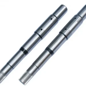
How Is the Pump Shaft Manufacturing Process Carried Out?
The manufacturing of a pump shaft follows a highly controlled and precise workflow to ensure strength, accuracy, and long service life in demanding operating environments. Below is a restructured version of the production process on the shaft, rewritten with differentiated wording while preserving all key technical concepts and SEO keywords.
Raw Material Preparation
The process begins with selecting high-strength steel bar stock, which is then cut into predefined lengths according to specific shaft designs and pump engineering requirements. Only industrial-grade materials are chosen to ensure the shaft can resist heavy loads, corrosion, and continuous operation in industrial, agricultural, and municipal pumping systems.
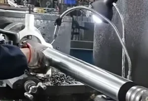
CNC Lathe Precision Turning
In this stage, the shaft blank is mounted onto an advanced CNC lathe for high-precision machining. The shaft production process on CNC lathe involves forming critical features such as diameters, shoulders, grooves, and threaded sections. All dimensions are controlled within extremely tight tolerances, ensuring perfect alignment with bearings, seals, impellers, and sleeves during final assembly.
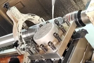
Milling and Secondary Machining Operations
After turning, the semi-finished shaft is transferred to CNC milling equipment for further structural detailing. This includes machining keyways, cross-holes, and other functional features based on design specifications. These customized modifications are essential for application-specific pump models, ensuring compatibility with different hydraulic and mechanical configurations.
Dimensional Inspection and Quality Control
Before moving forward, every component undergoes strict inspection under a comprehensive quality control process on shaft production. Precision measuring instruments such as micrometers, digital calipers, and coordinate gauges are used to verify dimensional accuracy. This ensures that issues like vibration, imbalance, or misalignment are eliminated before assembly.
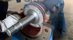
Dynamic Balancing Process
For shafts used in high-speed or large-capacity pump systems, dynamic balancing is performed. The shaft balancing process in manufacturing helps optimize weight distribution along the axis, reducing vibration and improving operational stability. Specialized balancing machines are used to achieve smooth rotation and extend service life.
Surface Finishing, Cleaning, and Packaging Preparation
In the final stage, the shaft is carefully deburred to remove sharp edges, thoroughly cleaned to eliminate machining residues, and properly marked for identification. Once finished, it is prepared for assembly integration with matching pump components, ensuring reliable performance and long-term durability in real-world applications.
Why Are Engineering Tolerances and Balancing Important for Pump Shafts?
In precision pump manufacturing, maintaining strict dimensional control is essential to ensure that components fit and function correctly within the overall system. The Engineering Tolerances and Balancing process focuses on achieving highly accurate geometrical consistency so that the shaft can operate smoothly within assemblies without causing misalignment or operational stress.
Tight engineering tolerances help ensure that the shaft interfaces precisely with surrounding components such as bearings, seals, and impellers. Even minor deviations in diameter, concentricity, or straightness can affect system performance, making precision control a critical requirement during manufacturing.
At the same time, shaft balancing is performed to optimize rotational stability. Proper balancing significantly reduces vibration during high-speed operation, which directly improves system efficiency and mechanical reliability. By eliminating uneven mass distribution, the shaft experiences less dynamic stress, resulting in smoother performance.
What Role Do Heat Treatment and Surface Finishing Play in Pump Shafts?
To improve the mechanical reliability and service life of pump shafts, a combination of thermal processing and surface engineering techniques is commonly applied under the Heat Treatments and Surface Finishes process.
Heat treatment methods such as quenching and tempering are used to modify the internal structure of the metal. This controlled heating and cooling cycle enhances overall hardness, increases tensile strength, and improves the shaft’s ability to withstand repeated torsional and axial stresses during operation. As a result, the component becomes more resistant to deformation and fatigue failure under heavy-duty conditions.
In addition to thermal processing, surface finishing techniques play a critical role in performance optimization. Processes such as fine polishing and surface smoothing help reduce friction between moving components, allowing for more efficient rotation. At the same time, a refined surface layer improves resistance to corrosion, particularly in environments exposed to moisture, chemicals, or abrasive fluids.
When combined, these Heat Treatments and Surface Finishes not only strengthen the internal structure of the shaft but also enhance its external durability, ensuring stable performance and extended service life in demanding pumping applications.
A well-balanced shaft also reduces unnecessary wear on connected pump components. This not only extends the operational lifespan of the entire system but also lowers long-term maintenance frequency and associated costs, making Engineering Tolerances and Balancing a key factor in ensuring durable and efficient pump operation.
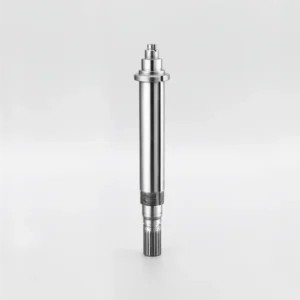
What Is Pump Shaft Quality (PSQ) in Manufacturing Standards?
Pump Shaft Quality (PSQ) refers to a precision manufacturing standard where the shaft undergoes multiple finishing processes, including turning, grinding, and polishing, to ensure it meets the strict requirements of rotating machinery applications. This level of finishing is essential for achieving consistent performance in high-speed and load-sensitive systems.
During the grinding stage, the shaft is refined to achieve extremely tight dimensional accuracy. This process improves diametrical tolerance control, reduces surface irregularities, and significantly lowers the risk of friction-related wear during long-term operation. As a result, the shaft operates more smoothly and maintains stability under continuous rotational stress.
In addition, each shaft is carefully straightened after machining to ensure optimal geometric alignment. This step is crucial for minimizing vibration along the shaft length, especially in high-speed or high-load environments where even slight deviation can impact system efficiency and component lifespan.
Whether produced from stainless steel bar stock or other high-performance materials, Pump Shaft Quality (PSQ) ensures that every shaft is manufactured to strict standards of straightness, surface finish, and diameter precision. This guarantees reliable performance across various rotating equipment applications where accuracy and durability are critical.
What Are the Key Applications and Benefits of Pump Shafts?
The use of engineered pump shafts spans a wide range of industrial and commercial environments where reliable fluid movement is essential. In the context of Applications and Benefits, these components are widely implemented in systems such as petrochemical processing facilities, water treatment infrastructure, and HVAC circulation networks. Each application places different demands on the shaft, requiring tailored mechanical performance to ensure stable operation under varying pressure, temperature, and load conditions.
In industrial settings, custom-designed shafts are particularly valuable because they can be adapted to match specific operational requirements. This adaptability allows the shaft geometry, material selection, and structural features to be optimized for each use case, ensuring consistent performance even in harsh or high-demand environments.
From a performance standpoint, Applications and Benefits highlight the importance of customization in improving overall system efficiency and reliability. By aligning shaft design with pump specifications, compatibility issues are significantly reduced, which in turn minimizes downtime and mechanical failures. This targeted engineering approach leads to smoother operation, improved energy efficiency, and a more stable pumping system throughout its service life.
How to Choose the Best Pump Shaft for Your Application?
Selecting the right shaft solution depends heavily on real operating conditions rather than a single design factor. Parameters such as load type, rotational speed, operating temperature, and environmental exposure all directly influence performance, stability, and service life. A mismatch between shaft design and application conditions can quickly lead to vibration issues, premature wear, or even system failure.
In applications where rotating components require stable support and smooth motion transfer, bearing shaft systems are commonly used. These setups are typically found in equipment such as conveyor systems, turbines, and electric motors, where the primary requirement is controlled rotation with reduced friction and consistent alignment under moderate loads.
On the other hand, pump shafting for high torque and axial load applications is specifically designed for more demanding environments. These shafts are engineered to handle continuous heavy-duty operation, making them suitable for industries such as oil and gas extraction, chemical processing plants, and wastewater treatment facilities. In these scenarios, the shaft must resist both torsional stress and axial thrust while maintaining long-term dimensional stability.
Ultimately, choosing between different shaft types requires a clear understanding of the mechanical demands of the system. Matching the correct shaft design to the application ensures higher efficiency, improved reliability, and reduced maintenance risks over the lifecycle of the equipment.
What Does Welleshaft Offer for Pump Shaft Manufacturing in China?
At welleshaft China, a wide range of precision-engineered stainless steel bar stock is available, specifically processed to meet Pump Shaft Quality (PSQ) requirements. These materials are designed for use in demanding rotating equipment applications where strength, dimensional accuracy, and long-term stability are critical.
The available Pump Shaft Quality (PSQ) materials in China are supplied in standardized diameters and lengths to support diverse industrial applications. These stainless steel grades provide excellent resistance to corrosion, helping protect the shaft from environmental exposure, moisture, and chemically aggressive operating conditions, thereby extending overall service life.
Typical material options include:
- 17-4 PH stainless steel
- SS 316
- SS 410
- SS 416
- Alloy 20
- 2205 Duplex stainless steel
- K500 Monel
In addition to standard specifications, welleshaft China also provides non-standard shaft sizes that can be fully customized through precision machining. These custom Pump Shaft manufacturing solutions in China allow components to be produced according to exact engineering drawings, ensuring compatibility with specific industrial requirements.
Different stainless steel grades and machining finishes are available to match application-specific performance needs, allowing shafts to be optimized for corrosion resistance, mechanical strength, and operational durability across a wide range of industrial environments.
FAQ of Pump Shaft
What are the benefits of using a Pump Shaft?
A well-designed Pump Shaft plays a vital role in improving overall system efficiency by ensuring smooth power transmission with minimal energy loss. It also enhances operational stability, reduces maintenance frequency, and provides strong resistance to corrosion and mechanical fatigue, making the pump system more reliable over time.
How do I choose the right Pump Shaft for my application?
Selecting the correct Pump Shaft for specific applications depends on several engineering factors, including fluid characteristics, pump size, load requirements, and working environment. Proper selection ensures compatibility with system conditions and helps prevent performance issues. Consulting engineering specifications or technical experts is recommended for accurate matching.
How do I maintain my Pump Shaft?
Proper maintenance of a Pump Shaft is essential to extend its service life and maintain stable performance. Regular inspection helps detect early signs of wear, corrosion, or misalignment. Cleaning, correct lubrication, and alignment checks are necessary to reduce friction, prevent vibration, and avoid premature failure in long-term operation.
This blog was provided by the Welleshaft Engineering Team led by Mr. Zhang, with over 10 years of experience in precision shaft manufacturing, CNC machining, and industrial pump component solutions across global markets.
Avis
Il n’y a pas encore d’avis.