
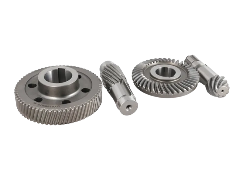
What Are Helical Gears and Their Selection Factors?
A helical gear transfers motion and torque between shafts in mechanical power transmission systems by using angled teeth on a cylindrical gear body. Engineers typically combine multiple gears into a gear train to regulate speed, increase torque, and control the direction of power transmission.
Unlike spur gears with straight teeth, manufacturers cut helical gear teeth at an angle relative to the shaft axis, creating the helix angle that defines their unique tooth geometry.
This angled geometry allows the teeth to engage gradually rather than all at once. The result is a smoother transfer of force, reduced impact at the point of contact, and improved running stability during operation.
In practical applications, helical gears are widely used for both speed increase and torque multiplication or reduction. Depending on gearbox design, they can operate in parallel-shaft or intersecting/cross-shaft configurations. This flexibility makes them suitable for compact mechanical systems where efficiency and space utilization are both important.
A key performance feature of helical gears is their higher contact ratio. Because more than one tooth pair is in contact during operation, the load is distributed across a larger surface area. This reduces stress concentration on individual teeth, improves load-carrying capacity, and helps extend service life. At higher operating speeds, this also contributes to quieter and smoother performance compared to spur gear systems.
How helical gears work in a gear train?
Engineers use the gear ratio to control how a gear system converts input speed into output torque. The ratio depends on the number of teeth on each interacting gear. During power transmission, the gear train transfers mechanical energy efficiently, with only minor energy losses from friction and heat.
During engagement, the teeth of a helical gear make contact gradually from one side of the tooth face to the other. This progressive meshing reduces sudden shock loads and spreads the force more evenly across multiple teeth. As a result, the system achieves smoother motion transmission and better stability, especially in continuous-duty or high-speed applications such as industrial drives and heavy machinery.
However, the angled tooth design also introduces axial thrust force, which is not present in spur gears. This axial load must be accounted for in mechanical design. Bearings such as thrust bearings or tapered roller bearings are commonly used to support both radial and axial forces. The size of the helix angle directly affects this behavior—larger angles improve smoothness and load capacity but increase axial thrust requirements.
Lubrication is another critical factor in helical gear operation. Since the tooth contact involves both rolling and sliding motion, insufficient lubrication can lead to higher friction, temperature rise, and accelerated wear. Proper lubrication design helps maintain efficiency and ensures reliable performance in demanding environments such as compressors, conveyors, automotive drivetrains, and industrial gearboxes.
Selecting the right helical gear
Selecting a suitable helical gear requires careful consideration of multiple design parameters. Key factors include number of teeth, module (or diametral pitch), pitch diameter, face width, helix angle, center distance, and material selection. These parameters directly influence gear ratio, torque capacity, noise level, backlash, and overall durability of the system.
Operating conditions are equally important in the selection process. Load characteristics, rotational speed, lubrication method, working temperature, and maintenance frequency all affect gear performance and service life. A properly matched design ensures stable operation, reduced wear, and long-term reliability of the entire gear train, particularly in high-load and high-speed mechanical systems.
What are the advantages and disadvantages of helical gears?
Engineers choose helical gears for modern mechanical systems because these gears provide smooth operation and high load-carrying capacity. However, designers must consider the potential trade-offs in performance, cost, and application requirements during the design process.
Advantages
One of the most notable helical gear advantages is their quiet and smooth operation. Manufacturers and engineers prefer helical gears over other gear types because these gears minimize noise and vibration while ensuring smooth, stable operation in large-scale production environments.
Another important benefit is their ability to transmit power between shafts that are not strictly parallel. This flexibility in shaft alignment allows engineers to design more adaptable systems, although it may sometimes lead to slightly reduced efficiency depending on the configuration.
Thanks to their angled tooth design, helical gears can better manage axial forces generated during rotation. This makes them particularly suitable for applications involving high-speed movement, heavy material handling, or machinery that operates continuously under load.
In heavy-duty industries such as construction and industrial manufacturing, helical gears are commonly chosen due to their strong torque transmission capability. Their staggered tooth contact distributes load more evenly, allowing them to perform reliably in demanding working conditions.
Compared with spur gears, helical gears also offer higher strength performance. The diagonal tooth structure increases the effective contact area, enabling the gear to handle greater loads without increasing size. This makes them advantageous when compact yet powerful transmission is required.
The helical gear design flexibility is another key advantage.Designers arrange helical gears in parallel or intersecting shaft configurations according to specific application requirements. This design flexibility allows engineers to optimize mechanical layouts and improve system adaptability.
In automotive systems, manufacturers use helical gears to transmit motion and power between shafts positioned at different angles. Their smooth engagement helps automotive drivetrains deliver stable performance and efficient power transmission.
Disadvantages
Despite their advantages, helical gears also come with several limitations that affect design and maintenance.
Due to the helix angle, meshing gear teeth generate axial thrust during operation. This requires the use of specialized bearings capable of handling and absorbing these additional forces, which increases system complexity.
Another drawback is the sliding contact that occurs between meshing teeth. This sliding action produces more heat compared to spur gears, which means proper lubrication is essential to ensure stable performance and reduce wear over time.
In terms of efficiency, helical gears generally perform slightly lower than equivalent spur gears. The increased friction and sliding contact result in additional energy loss during power transmission.
Similarly, helical gear systems may experience higher overall power loss compared to simpler spur gear setups, especially in long-duration or high-load operations.
From a manufacturing perspective, both the design and production of helical gears are more complex and costly. The precision required for the angled tooth geometry increases machining difficulty, which directly impacts production cost compared to standard gear types.
Why choose helical gears over spur gears in mechanical design applications?
When selecting components for a power transmission system, the decision between spur gears and helical gears is one of the most important design choices. Both serve the same basic function, but their tooth geometry leads to very different operating behavior.
Spur gears are straightforward in design and do not generate axial force. Designers typically select these gears for simple or low-speed applications where noise control and smooth operation are not major concerns. However, engineers prefer helical gears for systems that demand smoother motion, greater load capacity, and quieter performance.
In many practical applications, especially where speed and performance matter, helical gears tend to deliver more stable and efficient results.
Core differences between spur gears and helical gears
The key distinction comes from the tooth orientation. Spur gears have straight teeth that engage all at once, while helical gears use angled teeth that gradually come into contact.
| Feature | Spur Gears | Helical Gears |
| Noise level | Higher | Lower |
| Load capacity | Gut | Higher |
| Axial force | None | Present |
| Efficiency | Hoch | Slightly reduced |
These differences may seem simple, but they directly affect vibration behavior, durability, and overall transmission quality.
How tooth design affects performance
The angled teeth in helical gears create a more progressive engagement. Instead of the entire tooth face meshing instantly, contact begins at one point and spreads smoothly across the surface.
This gradual engagement helps reduce shock loading and eliminates the sharp “gear whine” often associated with spur gears, particularly in high-speed operation. It also increases the contact ratio, meaning multiple teeth share the load at the same time, improving stability.
Load capacity and transmission advantages
Because more teeth are engaged simultaneously, helical gears can transmit higher loads compared to spur gears of similar size. This makes them suitable for compact designs where power density is important.
In many engineering applications, this advantage allows smaller gearboxes to handle the same or even higher torque levels, improving space efficiency without sacrificing performance.
The trade-off: axial thrust in helical gears
Despite their advantages, helical gears introduce an important design challenge: axial thrust. The angled teeth generate a force along the gear shaft during operation.
This additional force does not exist in spur gear systems and must be managed using appropriate bearing arrangements, often including thrust bearings alongside radial bearings. If not properly controlled, it can lead to increased wear and reduced system life.
This makes Helical Gears Design more complex, as engineers must balance smooth operation with proper axial load management.
Spur gears vs helical gears in practical use
| Aspect | Spur Gear | Helical Gear |
| Tooth engagement | Instant full contact | Gradual contact |
| Vibration level | Higher vibration | Lower vibration |
| Bearing requirements | Radial bearings only | Radial + thrust bearings |
| Typical applications | Low-speed, simple systems | High-speed, quiet operation |
In essence, spur gears are simpler and easier to implement, especially where cost and axial simplicity are priorities. However, helical gears provide smoother motion, quieter operation, and better load distribution thanks to their angled tooth design.
The main compromise is the presence of axial thrust, which adds design complexity but is often justified in high-performance and high-speed mechanical systems.
What are the main applications of helical gears in industrial systems?
Helical gears are widely used across industries where smooth power transmission, high load capacity, and stable high-speed performance are required. Their angled tooth design allows gradual engagement, which reduces vibration and improves efficiency in continuous operation systems.
High-speed and fast-paced industries
Designers select helical gears for high-speed mechanical systems because they reduce noise and minimize wear compared with other gear types. Engineers rely on their stable load-bearing contact to support equipment operating at elevated rotational speeds, particularly in applications that demand continuous and consistent torque transfer over extended operating periods.
Pump systems with helical gears
In pumping applications, helical gears help improve flow consistency by ensuring smoother and more continuous tooth engagement. The overlapping contact between gear teeth reduces pulsation during discharge, supporting a more stable output flow. This design also allows pumps to achieve higher capacity while maintaining compact gear structures with fewer but stronger teeth.
Industrial chemistry and processing equipment
Within chemical processing systems, helical gears are commonly used in drives for compressors and turbines. Their role is often to regulate speed, allowing mechanical equipment to match the operating requirements of motors and generators. In these environments, reliable cooling and effective lubrication are critical to manage heat buildup and ensure stable long-term operation under continuous load conditions.
Automotive applications
In the automotive industry, helical gears are widely adopted in transmissions and drivetrain systems due to their strength and durability. The multiple tooth engagement increases the contact surface area, which helps distribute load more evenly under high torque conditions. This makes them suitable for vehicles that require smooth gear shifting, high efficiency, and long service life under varying driving conditions.
General industrial and production machinery
Helical gears are also commonly used in manufacturing and production equipment that operates under heavy load or continuous duty cycles. Their design allows them to handle combined rotational and axial forces effectively, making them suitable for machinery involving high-speed rotation, heavy material handling, or uninterrupted operation. The result is improved stability, reduced mechanical stress, and longer equipment lifespan in demanding industrial environments.
What are the fundamental geometric parameters of a helical gear?
The performance of a helical gear is determined by a set of basic geometric parameters that define its shape, tooth structure, and meshing behavior. These values are not just design references—they directly influence manufacturability, strength, and transmission quality.
A clear understanding of these parameters is essential for accurate helical gears design and reliable production outcomes.
Helix angle: the key geometric feature
The helix angle is the most distinctive characteristic of helical gears. It refers to the inclination of the teeth relative to the gear axis.
Unlike straight-tooth designs, this angled structure allows gradual tooth engagement, which improves smoothness and reduces noise during operation. A larger or smaller helix angle will also affect axial force generation and load distribution.
Pitch and module: defining tooth size and spacing
To ensure proper meshing between gears, both pitch and module must be carefully defined.
Pitch represents the spacing between adjacent teeth, while module serves as the standardized metric used to describe tooth size.
| Parameter | Description |
| Normal pitch | Distance between teeth measured perpendicular to the tooth direction |
| Transverse pitch | Distance between teeth measured along the pitch circle |
Correct alignment of these values ensures stable meshing and consistent motion transfer.
Key geometric parameters in helical gear design
Beyond basic sizing, several additional parameters refine performance and control how the gear behaves under load.
Pressure angle
Gear designers select the pressure angle to control force transmission between mating teeth and optimize tooth profile geometry. Although manufacturers commonly produce helical gears with a 20° pressure angle, engineers may choose different angles for specialized applications that require greater load capacity and enhanced durability.
This parameter has a direct impact on strength, contact stress, and smoothness of operation.
Module: normal vs transverse definition
The module also has two important variations: normal module and transverse module.
- Normal moduleis measured perpendicular to the tooth surface
- Transverse moduleis measured in the plane of rotation
For proper meshing, mating helical gears must share the same normal module, ensuring geometric compatibility and smooth engagement.
Addendum and dedendum: defining tooth height
Tooth height is controlled by two parameters:
- Addendum: the portion of the tooth above the pitch circle
- Dedendum: the portion below the pitch circle
Together, they define the working depth of the gear tooth and the clearance required during meshing. Proper balance of these values helps avoid interference and ensures stable operation.
These fundamental parameters form the structural basis of helical gears design. From helix angle to module selection, each factor plays a role in defining how the gear performs under load, how smoothly it operates, and how efficiently it transmits motion.
What is the function of the helix angle in a helical gear system?
The helix angle is one of the most influential design parameters in a helical gear system. It is not an arbitrary geometric choice—it directly shapes how the gear transmits motion, handles load, and behaves under speed.
The helix angle represents a constant trade-off between smooth operation and axial force. Any adjustment to this angle will immediately affect performance characteristics such as noise level, load capacity, and bearing requirements.
How the helix angle affects gear performance
The helix angle controls how teeth come into contact during rotation. This changes both the quality of engagement and the type of forces generated.
- A larger helix angle improves smoothness and reduces vibration, making operation quieter
- A smaller helix angle reduces axial thrust and supports higher load capacity
However, neither option is universally better. Each comes with its own mechanical compromises that must be evaluated during helical gears design.
Trade-off between load capacity, noise, and axial thrust
The impact of different helix angles can be summarized as follows:
| Helix Angle Range | Advantages | Limitations |
| Low angle (e.g., < 20°) | Higher load capacity, lower axial thrust | More noise, less smooth engagement |
| High angle (e.g., > 30°) | Quiet operation, smoother meshing | Increased axial thrust, lower load capacity |
This balance is a key consideration when designing gear systems for different operating conditions.
Selecting the right helix angle for applications
Choosing the correct helix angle depends entirely on the intended application. There is no universal standard that fits all operating environments.
In practice, engineers adjust the angle based on whether the priority is speed, load resistance, or vibration control.
High-speed applications
In high-speed systems such as automotive transmissions, larger helix angles are commonly used, often in the range of 30° to 45°.
This configuration improves the contact ratio between gear teeth, resulting in smoother power transfer and significantly reduced noise and vibration. However, it also increases axial thrust, which must be managed through appropriate bearing design.
High-load industrial applications
For heavy-duty machinery and industrial equipment, smaller helix angles—typically between 15° and 25°—are more common.
This setup prioritizes strength and durability by maximizing load-carrying capacity while keeping axial thrust at a more manageable level. It is often preferred in systems where long-term mechanical stability is more important than noise reduction.
Application-based helix angle selection
| Anmeldung | Typical Helix Angle | Main Objective |
| Automotive gearbox | 30° – 45° | Noise reduction and smooth operation |
| Industrial conveyor systems | 15° – 25° | Load capacity and durability |
| Precision robotics | 20° – 35° | Balance between smooth motion and strength |
What forces act on a helical gear during operation?
When helical gears are in mesh, the contact between teeth does not generate a single simple force. Instead, the load on the tooth surface resolves into a combined resultant force that can be broken down into three fundamental components.
Separating these force directions is essential for understanding how the gear system behaves in real operating conditions. Each force influences different parts of the mechanism, including shafts, bearings, and the gear body itself.
The three main force components in helical gears
For engineering analysis, the resultant load is divided into three primary force vectors:
| Force component | Main role in the system |
| Tangential force | Transfers torque and power |
| Radial force | Pushes gears apart |
| Axial force (thrust) | Moves gear along shaft direction |
Each of these forces must be accounted for individually to ensure a stable and reliable design.
Why force analysis is critical in helical gears design
Force distribution is not just a theoretical calculation—it directly determines component life and system stability. If one force component is underestimated, the result can be premature wear or structural failure.
A proper helical gears design process always begins with breaking down these loads to understand how stress is distributed across the system.
Tangential force (Wt): the torque transmission force
The tangential force is the primary working force in a gear system. It is responsible for transmitting power between meshing gears.
This force is directly related to torque and acts along the direction of rotation. It is the component that actually enables motion transfer from the driving gear to the driven gear.
If this force exceeds material limits, tooth failure or shaft torsion damage may occur.
Radial force (Wr): separation force between gears
The radial force acts toward the center of the gear. Instead of contributing to rotation, it pushes the two gears away from each other.
Shaft bearings handle most of this load, so engineers must account for it during gear system design. When designers underestimate radial loads, they risk causing premature bearing fatigue and excessive shaft deflection during long-term operation.
Proper bearing selection and shaft stiffness are critical for managing this force effectively.
Axial force (Wa): the thrust unique to helical gears
The axial force, also known as thrust force, is a distinctive characteristic of helical gears design. Because of the angled tooth geometry, this force acts along the shaft axis.
Unlike spur gears, helical gears require specific bearing arrangements—such as thrust or angular contact bearings—to control axial movement. If not properly managed, it can lead to misalignment, overheating, or accelerated bearing failure.
The magnitude of this force is influenced by parameters such as the normal pressure angle and helix geometry.
Force impact summary in gear design
| Force type | Design focus | Possible failure risk |
| Tangential force | Torque transmission, tooth strength | Tooth breakage, shaft torsion |
| Radial force | Bearing capacity, shaft rigidity | Bearing wear, fatigue failure |
| Axial force | Thrust control, housing support | Misalignment, overheating |
Engineering insight
In practical applications, the axial force is often the most underestimated factor in early design stages. When not properly addressed, it can become the root cause of unexpected system failures.
A reliable helical gears design must therefore consider all three force components together, ensuring that shafts, bearings, and housings are correctly matched to the actual load conditions.
What are the different types of helical gears used in engineering?
Gear designers classify helical gear designs according to shaft arrangements and motion transfer methods. These shaft configurations determine how gears engage, distribute loads, maintain efficiency, and perform in different applications.
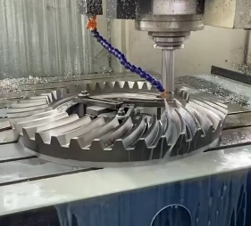
In industrial applications, engineers typically categorize helical gears into parallel-axis, crossed-axis, and specialized configurations, including double helical gears, herringbone gears, rack and pinion systems, screw gears, worm drives, and bevel helical gear systems.
How are helical gears classified based on shaft arrangement?
The most fundamental distinction lies in whether the shafts are parallel or non-parallel. This difference defines the type of contact and overall transmission behavior.
| Gear type | Shaft arrangement | Contact type |
| Parallel axis | Parallel shafts | Line contact |
| Crossed axis | Non-parallel, non-intersecting shafts | Point contact |
Even this basic structural variation has a direct impact on efficiency, wear behavior, and torque-handling capability.
Parallel axis helical gears: the most widely applied system
Parallel axis systems represent the most common form of helical gears used in power transmission. They are designed for shafts that rotate in parallel alignment.
To ensure proper meshing, one gear must have a left-hand helix while the mating gear uses a right-hand helix. This opposite orientation maintains continuous engagement and stable motion transfer.
Key advantages include:
- High transmission efficiency
- Strong load-carrying capability
- Smooth and stable operation
Because of these benefits, parallel axis systems are widely used in gearboxes, speed reducers, and industrial drive units.
Crossed-axis helical gears: transmission between non-parallel shafts
Crossed-axis systems are used when shafts neither intersect nor run parallel. These are often referred to as screw-type gear arrangements in practical applications.
A notable feature is that both gears may share the same helix direction, unlike parallel systems. However, contact occurs at a single point, which reduces load capacity and increases sliding friction.
This configuration requires careful consideration of axial thrust, which becomes more significant under load and must be managed through proper bearing selection.
Typical characteristics include:
- Lower torque transmission capability
- Reduced efficiency due to sliding contact
- Increased wear under heavy load conditions
These systems are generally suited for light-duty motion transfer rather than high-power applications.
Double helical gears: eliminating axial thrust through symmetry
Double helical gears are designed to counteract axial thrust by combining two opposite helical sections on the same gear body.
The opposing helix angles generate equal and opposite axial forces, effectively neutralizing thrust and stabilizing shaft loading.
Key benefits include:
- High load capacity
- Smooth and continuous torque transmission
- Reduced vibration and noise
- Improved bearing service life
Due to these advantages, they are widely used in turbines, compressors, and marine propulsion systems.
Manufacturing requires precise alignment between both helix sections, making production more complex compared to standard helical gears design.
Herringbone gears: integrated double helical structure
A herringbone gear is a specialized form of double helical gear where the two opposing helices are joined into a continuous V-shaped tooth profile.
This integrated structure completely removes axial thrust while maintaining uninterrupted tooth contact during operation.
Main advantages include:
- Zero net axial load
- High torque transmission capability
- Excellent stability at high speeds
- Low vibration and high durability
These gears are commonly used in heavy-duty industrial equipment such as rolling mills, marine drives, and large power transmission systems.
Helical rack and pinion systems: rotational to linear motion conversion
A helical rack and pinion system converts rotational motion into linear movement. The pinion uses helical teeth, while the rack is a straight component with matching angled geometry.
Compared with straight-cut systems, helical versions provide smoother engagement and reduced vibration due to gradual tooth contact.
Key features include:
- High positioning precision
- Quiet and smooth linear motion
- Improved load distribution
- Suitable for long stroke applications
These systems are widely applied in CNC machinery, robotics, automation systems, and automotive steering mechanisms.
Screw gears: cross-axis sliding transmission systems
Screw gears consist of helical gears mounted on non-parallel, non-intersecting shafts, often arranged at right angles. Their operation relies heavily on sliding contact between tooth surfaces rather than pure rolling.
Because of this sliding action, efficiency is lower, but motion remains smooth and quiet. However, wear characteristics are more pronounced, requiring appropriate lubrication and bearing support.
Key points include:
- Suitable for moderate speed and light-to-medium torque
- Compact design for space-limited assemblies
- Higher lateral forces requiring careful support design
- Permits axial movement during operation
These systems are often used in precision instruments and compact mechanical drives.
Helical worm gears: high reduction and torque multiplication systems
Helical worm gears combine a worm (screw-like shaft) with a worm wheel to achieve large speed reduction ratios and high torque output.
Reduction ratios can range from 20:1 to over 300:1, making them suitable for heavy reduction applications.
Key functional characteristics include:
- High torque multiplication
- Smooth and quiet operation
- Self-locking capability in many configurations
- Effective shock load absorption
Common applications include conveyors, elevators, crushing equipment, and industrial automation systems. However, efficiency is lower due to friction losses, making them more suitable for intermittent or low-to-medium power use.
Bevel helical gears: changing rotational axis direction
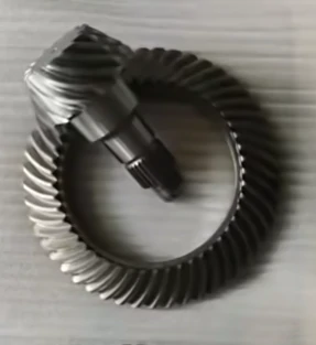
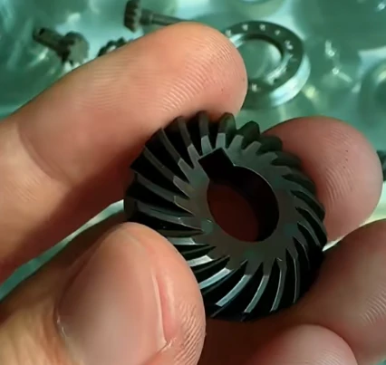
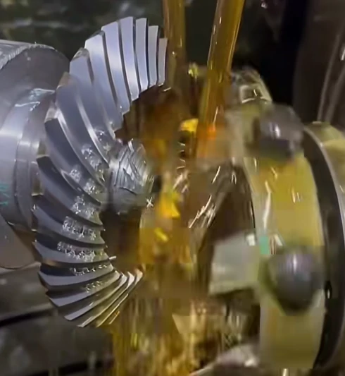
Bevel helical gears (spiral bevel gear systems) are used when power transmission requires a change in shaft direction, typically at a 90-degree angle.
These gears feature curved, spiral-shaped teeth on a conical surface, allowing gradual engagement and smoother transmission compared to straight bevel gears.
Key advantages include:
- High efficiency and power density
- Strong shock resistance
- Smooth and quiet operation
- Flexible shaft configuration options
They are widely used in mining machinery, steel production, automotive systems, and material handling equipment where directional power transfer is required.
Summary of helical gear types and applications
| Type | Key advantage | Main limitation | Typical application |
| Parallel axis helical gears | High efficiency and load capacity | Limited to parallel shafts | Industrial gearboxes |
| Crossed-axis helical gears | Flexible shaft layout | Lower efficiency, higher wear | Light-duty mechanisms |
| Double helical gears | Balanced axial thrust | Complex manufacturing | Turbines, compressors |
| Herringbone gears | Zero axial load, high stability | High production complexity | Heavy-duty drives |
| Rack and pinion (helical) | Precise linear motion | Thrust management required | CNC, robotics |
| Screw gears | Compact cross-axis motion | Lower efficiency | Precision instruments |
| Helical worm gears | High reduction ratio | Friction losses | Conveyors, lifts |
| Bevel helical gears | Directional power transmission | More complex geometry | Mining, automotive |
How do single helical gears compare with double helical (herringbone) gears?
The decision between single helical gears and double helical (herringbone) gears is a classic engineering compromise in Helical Gears Design. It usually comes down to balancing performance benefits against manufacturing complexity and cost.
Single helical designs are simpler and more economical, while double helical configurations are engineered for higher stability and smoother power transmission. The right choice depends heavily on load conditions, speed requirements, and system constraints.
Core difference: axial thrust behavior
The most important distinction lies in how each gear handles axial force.
A single helical gear naturally generates axial thrust during operation. This sideways force must be absorbed by external thrust bearings, which adds both mechanical complexity and cost to the overall system design.
In contrast, double helical gears (herringbone gears) use a mirrored tooth arrangement. The opposing helix angles generate equal and opposite forces, effectively canceling axial thrust within the gear itself.
This internal force balance removes the need for dedicated thrust-bearing support and simplifies shaft load management.
Performance comparison overview
| Feature | Single Helical Gear | Double Helical (Herringbone) Gear |
| Axial thrust | Present, requires external support | Self-balanced, no net thrust |
| Operating smoothness | Smooth operation | Extremely smooth and stable |
| Noise level | Mäßig | Very low |
| Cost level | Lower manufacturing cost | Higher production cost |
| Design complexity | Relatively simple | Structurally and geometrically complex |
Why axial thrust changes everything
In single helical systems, axial thrust becomes a key design constraint. Engineers must account for additional bearing loads, which influences shaft design, housing strength, and maintenance requirements.
Double helical gears eliminate this limitation by design. Since the axial forces cancel internally, the system no longer depends on external thrust compensation components. This allows more freedom in optimizing the overall transmission layout.
Performance advantages of double helical gears
Without axial thrust limitations, double helical gears can be designed with higher helix angles. A larger helix angle increases the contact ratio between teeth, meaning more teeth share the load at any given time.
This leads to several performance improvements:
- Smoother torque transmission
- Reduced vibration levels
- Improved load distribution
- Quieter overall operation
These advantages make herringbone gears particularly suitable for high-speed or high-torque applications where stability is critical.
Manufacturing complexity and challenges
Despite their performance benefits, double helical gears are significantly more difficult to manufacture. Achieving precise alignment between the left-hand and right-hand helices is critical.
Processes such as gear hobbing require specialized setups, tight synchronization, and high-precision machining to ensure both halves align perfectly.
Even small deviations in alignment can introduce uneven load distribution, increased stress concentration, or loss of the self-balancing effect.
Single helical gears, by comparison, are easier to machine and typically rely on standard production methods, which reduces lead time and cost.
Design trade-off summary
| Aspect | Single Helical | Double Helical |
| Thrust handling | Requires external bearings | Internally balanced |
| Helix angle flexibility | Limited | Higher possible angles |
| Manufacturing process | Standard machining | Specialized precision processes |
| Application range | General industrial use | High-speed, high-load systems |
Final design consideration
The selection between single and double helical gears ultimately depends on whether the priority is cost efficiency or maximum performance stability.
Single helical gears offer simplicity and affordability, making them suitable for standard applications. Double helical gears deliver superior smoothness and load capacity but require higher manufacturing investment.
This decision represents a fundamental trade-off between mechanical simplicity and high-performance capability.
How do you perform basic geometric design calculations for helical gears?
Geometric design calculations follow a structured engineering sequence rather than random trial. The process always starts from a few fundamental inputs, typically the gear ratio and the center distance between shafts, which define the overall geometry boundary of the system.
From these two constraints, all remaining parameters are derived step by step. Each decision affects the next, so the design is essentially an interconnected system where every variable must align.
Core design constraints
At the beginning, two values control the entire calculation:
- Required gear ratio (i):Defines the speed relationship and torque transfer between the two gears.
- Center distance (a):Sets the fixed spatial limit between the two shaft centers.
These two parameters act as hard boundaries. If they are not satisfied, the design cannot function correctly, regardless of other optimizations.
Step-by-step calculation logic
The process typically begins by fixing the known conditions: gear ratio and center distance. The next task is to determine a workable combination of module, tooth number, and helix angle that satisfies both constraints simultaneously.
A common starting point is the helix angle (β) when working with helical gear systems. In most practical designs, it is selected within a moderate range (often around 15° to 30°). This choice has a direct impact on load capacity, smoothness of operation, and axial force generation.
A higher helix angle generally improves meshing smoothness and reduces noise, but it also increases axial thrust, which must be accounted for in bearing and shaft design.
Iterative selection of key parameters
Once a preliminary helix angle is chosen, the next step is to determine the module. This involves linking:
- Transverse module (mt):Connected to the center distance requirement
- Normal module (mn):Linked to manufacturing tooling standards and cutting conditions
- Tooth number (z):Must remain an integer while satisfying the required gear ratio
Because these variables are interdependent, the process is rarely linear. Engineers often adjust module size, tooth count, and helix angle repeatedly until the system converges on a valid solution that satisfies both geometry and ratio conditions.
Parameter relationships in the final layout
During validation, several geometric relationships must align:
- Pitch diameter:Defined by module and tooth number combination
- Tooth count:Must remain whole numbers while matching the gear ratio
- Face width:Selected based on torque capacity and load conditions
If any of these do not match the constraints, the design must be revised and recalculated.
Practical engineering approach
In real engineering work, software is often used to accelerate these iterations. However, understanding the manual calculation logic remains essential. It allows engineers to verify outputs, identify unrealistic results, and ensure the design is physically feasible.
Overall, basic geometric design calculations rely on a controlled iterative process that begins with gear ratio and center distance, then gradually resolves module selection, tooth distribution, and helix angle into a complete and functional gear geometry.
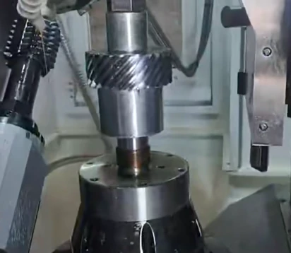
What are the key elements included in a gear specification sheet?
A gear specification sheet is more than just a technical document—it acts as the primary reference that connects design intent with actual manufacturing execution. This sheet serves as the “single source of truth,” ensuring that every requirement is clearly communicated to avoid misunderstandings during production.
Without a complete and accurate specification sheet, even small omissions can lead to dimensional errors, performance issues, or unnecessary manufacturing delays.
Fundamental gear data
The foundation of any gear specification sheet lies in its core geometric parameters. These values define the basic structure and functional behavior of the gear, and must be clearly defined without ambiguity.
Key parameters typically include:
- Number of Teeth (Z)– determines gear ratio and overall size
- Module (m)– relates the reference diameter to the tooth count
- Pressure Angle (α)– controls force transmission between meshing teeth
- Helix Angle & Hand (β)– defines tooth inclination and direction (left-hand or right-hand) in helical gear systems
These parameters form the geometric identity of the gear and directly influence meshing performance and load distribution.
Material selection and quality requirements
Beyond geometry, material choice and quality specifications define how the gear performs under real operating conditions. A specification sheet should clearly state:
- Base material type
- Required heat treatment process
- Expected hardness or strength level
- Quality grade or inspection standard
These factors directly affect durability, wear resistance, and service life. Even if geometry is correct, improper material or treatment selection can significantly reduce gear reliability.
Manufacturing tolerances
Tolerances are essential for defining acceptable variation in dimensions and geometry. They determine how precisely the gear must be manufactured.
In precision-driven applications, tighter tolerances are often required for tooth profile, pitch, and lead accuracy. However, stricter tolerances also increase machining difficulty and overall production cost.
In practical Helical Gears Design, engineers often balance performance requirements with manufacturability to avoid unnecessary cost escalation while maintaining functional reliability.
Heat treatment and surface finish specifications
Material selection alone is not sufficient to guarantee performance. Heat treatment processes such as carburizing or nitriding are commonly specified to improve hardness, fatigue strength, and wear resistance.
Surface finish requirements also play a significant role in reducing friction and improving meshing efficiency.
An important but sometimes overlooked parameter is the addendum modification coefficient, which helps prevent tooth interference in specific gear pair configurations and improves contact performance.
Gear quality standards and grades
Quality levels define inspection rigor and allowable deviation based on application requirements. Common classification systems such as AGMA or ISO standards are widely used to determine gear quality grades.
Typical quality levels include:
| Quality Level (AGMA) | Application Area |
| Q5 – Q7 | General industrial equipment, low-demand systems |
| Q8 – Q10 | Automotive transmissions, machine tools |
| Q11 – Q13 | High-speed or high-precision systems |
| Q14 – Q15 | Master gears, ultra-precision instruments |
Higher quality grades require stricter inspection processes and tighter tolerance control, which increases manufacturing cost but significantly improves performance consistency.
Why a complete specification sheet matters
A well-prepared gear specification sheet ensures that every design requirement is clearly translated into manufacturing instructions. It eliminates ambiguity between design and production teams and reduces the risk of rework or failure.
How do you determine the required gear quality level for helical gears?
Selecting the appropriate gear quality level is a key engineering decision that influences performance stability, service life, and manufacturing cost. It is essentially a balance between required precision and economic efficiency, rather than simply choosing the highest possible standard.
The selection is always driven by application conditions, especially speed, noise sensitivity, and functional importance. These factors define how strict the tolerance level must be for reliable operation.
Key factors affecting gear quality level selection
Three main parameters are typically used to define the required gear quality level:
- Operating speed
- Noise and vibration requirements
- Application criticality
Each factor directly influences how precise the gear must be to maintain stable meshing behavior.
| Factor | Lower Gear Quality Level | Higher Gear Quality Level |
| Operating speed | Acceptable for low-speed systems | Required for high-speed operation |
| Noise requirement | Tolerates more vibration | Requires smooth, low-noise transmission |
| Application criticality | Standard or non-critical use | High-reliability or safety-critical systems |
A higher AGMA or ISO quality grade means tighter dimensional tolerances, which reduces motion error and vibration. However, it also increases manufacturing difficulty and cost.
Relationship between precision and cost
Gear quality level is directly linked to production complexity. The cost does not increase gradually but rises sharply as precision requirements become stricter.
For example, moving from a mid-level grade (such as AGMA 8) to a higher grade (like AGMA 10) already requires more precise machining and inspection processes. When reaching AGMA 12 or above, finishing methods such as precision grinding and advanced metrology become necessary.
This makes it important to avoid over-specification, where unnecessary precision leads to excessive cost without real performance gain.
Influence of operating speed
High-speed gear systems are particularly sensitive to small geometric deviations. Even minor errors such as pitch variation can generate noticeable vibration and noise when rotational speed increases.
In high-speed applications—especially those exceeding approximately 2000 RPM—higher gear quality levels are typically required to maintain smooth meshing and reduce dynamic instability.
This is especially important in precision systems using helical gears, where consistent contact is essential for stable power transmission.
Noise sensitivity and application criticality
Some applications prioritize quiet operation over cost considerations. In such cases, tighter tolerances and higher gear quality levels are necessary to reduce vibration and acoustic emissions.
- Consumer electronics and medical devices often require low-noise performance
- Robotics and aerospace systems demand high reliability regardless of cost
In safety-critical environments, the required gear quality level is determined more by reliability expectations than by speed or noise alone.
Typical gear quality level ranges by application
Different industries generally follow predictable AGMA or ISO quality ranges:
| Application type | Typical AGMA quality range |
| Consumer products | 6 – 8 |
| Industrial machinery | 8 – 10 |
| Automotive / EV systems | 9 – 11 |
| Aerospace / medical systems | 11 – 13+ |
These ranges serve as practical reference points rather than fixed rules, helping engineers establish an initial design target.
Practical method for selecting gear quality level
A structured selection process can simplify decision-making:
- Define performance requirements
Start by identifying limits such as allowable noise, operating speed, load conditions, and expected service life. - Establish a baseline quality range
Use AGMA or ISO standards to map these requirements to an initial gear quality level range. - Evaluate manufacturability and cost
Compare the selected range with production capabilities and cost constraints to identify a realistic and efficient target level.
What are the common materials used for helical gears?
The selection of materials plays a decisive role in helical gear manufacturing. It directly influences load capacity, wear resistance, service life, and overall production cost. A suitable material choice ensures stable performance under different operating conditions, especially in demanding mechanical systems where reliability is critical.
In general, helical gears are commonly produced using three main material groups: steel-based materials, non-ferrous metals, and non-metallic engineering materials. Each category offers distinct performance characteristics depending on application requirements.
Steel Materials
Steel is the most widely used material family for helical gear applications, mainly due to its balance of strength, durability, and cost efficiency.
Carbon steel is one of the most common choices. It consists primarily of iron and carbon, offering moderate mechanical strength while remaining cost-effective. Because of its availability and ease of processing, it is extensively used in general-purpose gear manufacturing.
Alloy steel improves upon carbon steel by adding elements such as chromium, nickel, or molybdenum. These additions enhance hardness, wear resistance, and overall mechanical strength, making it suitable for heavy-load and high-stress environments.
Stainless steel contains a higher chromium content (typically above 10.5%), which provides strong resistance to corrosion. This makes it ideal for environments exposed to moisture, chemicals, or other corrosive conditions where rust prevention is essential.
Hardened steel is not a separate base material but rather steel that has undergone heat treatment processes such as quenching or carburizing. This treatment significantly increases surface hardness and wear resistance, improving the gear’s durability under continuous operation.
Non-Ferrous Metals
Non-ferrous metals are selected for helical gear material selection when weight reduction, corrosion resistance, or smoother operation is required.
Aluminum alloys combine aluminum with elements like magnesium or silicon. Their lightweight nature makes them suitable for applications where reducing rotational mass is important. They also offer moderate corrosion resistance and are relatively easy to machine.
Gear designers select copper alloys, such as brass and bronze, for specialized gear applications because these materials deliver excellent wear resistance and natural corrosion protection. Engineers use these alloys in moderate-load conditions where durability and reliability are required. However, manufacturers typically avoid pure copper and pure aluminum in gear production because their limited strength and poor wear resistance reduce performance under mechanical stress.
Non-Metallic Materials
Non-metallic materials are increasingly used in helical gear design where low noise, self-lubrication, or lightweight performance is required.
Nylon (polyamide) is a common engineering plastic known for its self-lubricating properties and good wear resistance. It also provides decent corrosion resistance, making it suitable for low- to medium-load applications where quiet operation is important.
Polyoxymethylene (POM) is another widely used thermoplastic with high dimensional stability and strength. It maintains its shape under load and resists deformation, making it suitable for precision gear systems that require consistent performance over time.
Phenolic resins (phenolics) are thermosetting plastics known for their excellent chemical resistance and low operating noise. They perform well in environments where exposure to oils, lubricants, or cleaning agents is common, while also helping reduce vibration and noise during operation.
How do you select appropriate materials and heat treatment for helical gears?
Selecting suitable materials and defining the correct heat treatment process requires a structured engineering approach. The goal is to ensure the gear can withstand real operating loads while maintaining durability over its entire service life. Instead of relying on assumptions, the selection is always driven by calculated stress data and validated material performance.
Start from stress analysis
The first step is to evaluate the working loads acting on the gear. Two primary stress types are used as reference:
- Bending stress:Indicates the risk of tooth root fracture under load
- Contact stress:Reflects surface durability and resistance to pitting
These calculated values form the baseline for all material decisions. Without this step, material selection becomes speculative and unreliable.
Use material data and engineering charts
Once stress levels are known, material selection is guided by standardized engineering references such as AGMA-based charts or equivalent data sources. These charts provide allowable stress limits for different steel grades and heat treatment conditions.
The objective is to identify a material–treatment combination that satisfies:
- Required allowable bending strength
- Adequate surface fatigue resistance
- Sufficient safety margin under real operating conditions
Role of safety margin in material selection
A safety factor is not an optional buffer but a necessary design requirement. It compensates for uncertainties such as:
- Load variation during operation
- Material property inconsistencies
- Manufacturing tolerances and surface quality differences
In most practical cases, a safety margin between 1.5 and 2.0 is commonly applied, depending on application severity and reliability requirements.
Matching steel grades with performance needs
Different steel materials respond differently to heat treatment, which directly affects gear performance. A structured comparison is often used to evaluate options:
| Material | Heat Treatment | Key Performance Characteristic |
| AISI 4140 | Quenched & tempered | Balanced strength and cost efficiency |
| AISI 8620 | Carburized & hardened | High surface hardness with good core toughness |
| AISI 9310 | Carburized & hardened | Excellent fatigue resistance and high-end performance |
Each combination represents a different balance between strength, toughness, cost, and service life. Selection depends on load level and expected fatigue conditions.
Understanding heat treatment processes
Material selection alone is not sufficient. Heat treatment determines the final mechanical behavior of the gear, especially in terms of surface hardness and core toughness.
Carburizing and hardening
This process introduces carbon into the surface layer of low-carbon steel. It produces a very hard outer shell while maintaining a relatively tough core. This combination is highly effective for resisting surface wear and fatigue while still absorbing shock loads.
Nitriding
Nitriding creates a hardened surface layer using nitrogen diffusion at relatively low temperatures. Because of the lower processing temperature, distortion is minimal. This makes it suitable for precision components where dimensional stability is critical.
Through hardening (quenching and tempering)
This method hardens the entire cross-section of the gear tooth. It provides uniform strength and toughness throughout the material. It is often selected for applications with moderate loads where cost efficiency is important.
| Heat Treatment | Surface Hardness | Core Toughness | Distortion Risk |
| Carburizing | Very high | Gut | Mäßig |
| Nitriding | Hoch | Variable | Low |
| Through hardening | Mäßig | Gut | Mäßig |
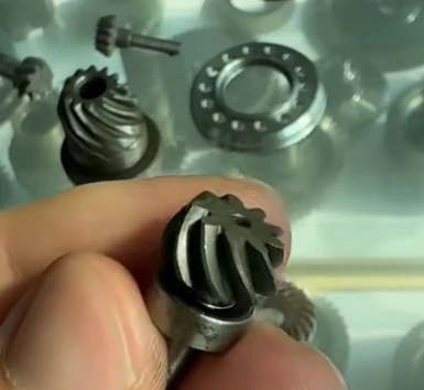
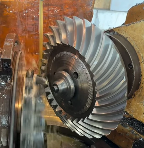
What factors should be considered when choosing materials for helical gears?
Selecting the right helical gear material is not a random decision. It directly affects performance, durability, noise level, and overall system efficiency. In practical engineering, material selection is always based on operating requirements rather than a single property.
Load Capacity
Engineers consider load-bearing capacity a key factor when they design gearboxes, reducers, and other torque-transmitting systems with helical gears. For high-stress applications, designers often choose alloy steel or hardened steel because these materials deliver excellent mechanical strength and maintain dimensional stability under continuous loading..
Rotating Speed
For high-speed machinery, material stability at elevated rotational speeds is essential. Gear designers select alloy steel and hardened steel for high-speed helical gear applications, including high-performance motors and aerospace-related drive systems, because these materials deliver the mechanical strength and dimensional stability needed to ensure reliable and smooth operation.
Noise Performance
Noise reduction is an important consideration in precision equipment. Engineering plastics such as nylon and POM are often selected due to their low friction characteristics. These materials help minimize vibration and noise, making them suitable for transmission systems in office equipment like printers and copiers where quiet operation is essential.
Working Conditions
Operating environments have a strong influence on helical gear material selection.Gear designers select heat-resistant materials, including alloy steel and stainless steel, for helical gear systems that generate significant heat during operation. Engineers apply these materials in fan gearboxes, conveyor drive systems, and other applications where thermal stability ensures reliable performance.
For marine, chemical, and other corrosive environments, engineers consider corrosion resistance a key material selection factor. Manufacturers choose stainless steel because the chromium in the alloy creates a protective surface layer that improves resistance to rust and chemical corrosion. In milder environments, designers may choose copper alloys or aluminum alloys to balance performance, weight, and cost.
Service Life Requirements
In applications requiring long-term continuous operation, durability becomes a key factor. For example, ship gear systems often operate under sustained heavy loads for extended periods. In such cases, alloy steel, hardened steel, or stainless steel are commonly selected due to their strong wear resistance and long service life performance.
Cost Considerations
Cost efficiency also plays an important role in helical gear material selection. Carbon steel and nylon are widely used in cost-sensitive applications, particularly in household appliances such as electric fans and washing machines. These materials help maintain acceptable performance while keeping production costs under control.
Lightweight Requirements
In modern equipment where weight reduction is critical, such as drones, robotic joints, and portable electric tools, aluminum alloys are frequently used. Their low density allows significant weight reduction without heavily compromising mechanical performance, making them ideal for compact and lightweight gear systems.
How do material choices structure the overall gear design process?
Material selection is one of the earliest and most influential decisions in helical gears design. It shapes not only mechanical performance but also manufacturing method, cost structure, service life, and operational limitations.
In practice, the choice of material defines the boundaries of what a helical gear can achieve in terms of strength, noise behavior, wear resistance, and load capacity. Every subsequent design step is built around this initial decision.
How are gear materials categorized in helical gears design?
Most materials used in helical gears manufacturing fall into three main groups. Each group serves different functional requirements depending on operating conditions.
| Material group | Key property | Typical application |
| Steels | High strength and durability | Industrial machinery |
| Engineering plastics | Low noise, self-lubricating | Consumer and light-duty systems |
| Bronze alloys | Low friction and wear resistance | Worm and sliding gear systems |
Why steel is the dominant material in helical gears manufacturing
Steel remains the most widely used material in helical gears manufacturing due to its strength and adaptability across different load conditions.
Low-carbon steels are easy to machine but often require surface hardening to improve wear resistance. Medium-carbon steels provide a better balance between toughness and strength. Alloy steels, however, are preferred for demanding applications where high stress and long service life are required.
Heat treatment plays a critical role in unlocking steel’s full performance potential, significantly improving hardness and fatigue resistance.
Typical advantages:
- High load-bearing capacity
- Excellent durability under stress
- Suitable for high-performance systems
This makes steel the foundation material for most industrial helical gears design applications.
Why plastics are used in low-noise helical gear systems
Engineering plastics such as nylon and acetal (POM/Delrin) are commonly used in applications where noise reduction and cost efficiency are more important than high load capacity.
These materials naturally reduce vibration and often provide self-lubricating behavior, reducing maintenance requirements.
Key characteristics:
- Low operating noise
- No external lubrication needed in many cases
- Cost-effective for mass production
Plastic gears are widely used in printers, household appliances, and medical devices where smooth and quiet operation is essential.
Why bronze is used in specific gear pair combinations
Bronze alloys play a specialized role, particularly in systems involving sliding contact, such as worm gear assemblies.
When paired with steel, bronze provides a low-friction interface that reduces wear and prevents surface damage like galling. Its ability to conform under load improves contact stability in sliding systems.
Typical advantages:
- Excellent anti-friction behavior
- Good compatibility with steel counterparts
- Stable performance in sliding contact applications
Bronze is often used in worm drives and systems where controlled wear behavior is more important than high strength.
Material comparison in helical gears design
| Material type | Strength level | Cost level | Key advantage |
| Carbon & alloy steels | Very high | Medium to high | High load capacity and durability |
| Engineering plastics | Low to medium | Low | Quiet operation and low maintenance |
| Bronze alloys | Medium | Hoch | Low friction in sliding contact |
This comparison highlights how material selection directly influences performance priorities in helical gears manufacturing.
How material choice influences the entire design process
Material selection determines more than just mechanical strength. It affects heat treatment requirements, manufacturing method, allowable tolerances, and even lubrication strategy.
For example, steel gears may require carburizing or induction hardening, while plastic gears are typically injection molded with minimal post-processing. Bronze components often rely on precise mating conditions to manage friction behavior effectively.
How are helical gears manufactured in modern production processes?
Manufacturers control the accuracy, surface finish, mechanical strength, and production efficiency of helical gears by selecting the appropriate manufacturing process. Engineers consider not only the production method but also the gear’s performance under actual operating loads when choosing a process.
Gear manufacturers select different production methods according to material characteristics, batch size, precision requirements, and application conditions. They use both conventional and advanced manufacturing technologies to optimize cost, durability, and overall gear performance.
What are the main manufacturing methods for helical gears?
In industrial production, helical gears manufacturing typically involves several core processes, each offering a different balance of precision, efficiency, and cost control.
| Process | Application focus | Production efficiency |
| Hobbing | Mass production | Hoch |
| Shaping | Internal or complex gears | Medium |
| Milling | Prototypes / small batches | Low |
| Grinding | Precision finishing | Low |
The final selection depends heavily on design requirements, tolerance targets, and expected service conditions.
Gear manufacturing overview: why process selection matters
Gear production is not a single-step operation. It involves a combination of forming, cutting, and finishing techniques, all of which directly affect tooth geometry, surface integrity, and long-term reliability.
Material selection (such as alloy steel, cast iron, or engineered polymers), production volume, and required gear grade all play a role in determining the right helical gears design route.
Casting: forming the initial gear blank
Gear manufacturers use casting to create the initial gear blank before performing precision machining operations. During casting, manufacturers pour molten material into a mold and form it into a near-net shape through controlled solidification.
While casting does not directly produce the final gear teeth, manufacturers rely on this process for large components where machining the entire part from raw material would increase cost and reduce production efficiency.
Typical characteristics:
- Suitable for large-size gear blanks
- Efficient for mass production of raw forms
- Requires secondary machining or finishing
Cast blanks are often used in heavy-duty equipment such as mining machinery, wind systems, and large industrial drives where toughness is more important than initial precision.
Forging: strengthening gear structure through deformation
Forging shapes metal through compressive forces after heating, producing a dense and strong internal grain structure. This improves fatigue resistance and overall durability of helical gears.
Depending on design requirements, forging can produce either near-finished shapes or semi-finished blanks.
Key advantages:
- High mechanical strength
- Excellent fatigue resistance
- Improved impact performance
Forged gears are commonly found in marine systems, heavy-duty transmissions, and high-load automotive applications where reliability under stress is critical.
Extrusion: continuous forming for uniform profiles
Manufacturers use extrusion to create long gear components with uniform cross-sections by pushing material through a precisely designed die.
In helical gear manufacturing, gear designers typically apply extrusion to produce racks and other elongated gear elements instead of conventional gear wheels.
Key characteristics:
- Suitable for long, uniform profiles
- Requires secondary machining for precision teeth
- Efficient for continuous production
It is often used in conveyor systems and linear motion mechanisms.
Powder metallurgy: near-net shape mass production
Powder metallurgy forms parts by compacting metal powder and sintering it below its melting point. This method is widely used in modern helical gears design for high-volume, small-to-medium size components.
Main advantages include:
- High material efficiency
- Low machining requirements
- Cost-effective mass production
However, it has limitations in size and load capacity, making it more suitable for compact gear systems such as electric motors, appliances, and small transmissions.
Machining processes: precision shaping of gear teeth
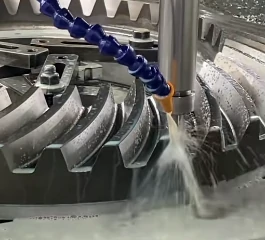
Machining remains one of the most important stages in helical gears manufacturing, especially for achieving accurate tooth geometry and controlled tolerances. CNC technology has significantly improved consistency and flexibility.
Common machining methods include hobbing, shaping, broaching, and milling.
Hobbing: high-efficiency gear cutting
Hobbing uses a rotating cutting tool (hob) that continuously generates gear teeth as it feeds into the rotating blank.
Key benefits:
- High production efficiency
- Stable and repeatable tooth quality
- Suitable for large-scale manufacturing
It is widely used in automotive, robotics, and industrial gearbox production.
Shaping: ideal for internal and complex gears
Shaping uses a reciprocating cutter to gradually form gear teeth. It is particularly useful when internal geometry prevents the use of hobbing tools.
Key features:
- Suitable for internal gears
- Flexible for complex geometries
- Lower productivity than hobbing
It is commonly used in planetary gear systems and compact transmissions.
Broaching: fast precision cutting
Broaching uses a multi-tooth tool that removes material in a single pass or sequence of passes, achieving high precision with excellent repeatability.
Typical applications:
- Small precision gears
- High-volume production
- Pump and medical device components
It is valued for speed and consistency in mass production environments.
Milling: flexible but less precise option
Milling forms gear teeth gradually using CNC-controlled cutting tools. While flexible, it is generally slower and less precise compared to other methods.
It is mainly used for:
- Prototyping
- Custom gear profiles
- Low-volume production
Despite limitations, CNC milling remains useful for experimental or specialized helical gears design projects.
Post-manufacturing processes: improving surface and performance
After machining, additional finishing steps are often required to enhance surface quality, accuracy, and wear resistance.
Common post-processing methods include:
- Grinding: improves dimensional accuracy and surface finish
- Lapping: enhances tooth contact precision using abrasives
- Honing: refines tooth geometry and reduces noise
- Shaving: removes micro-layer material for smoother profiles
- Burnishing: improves surface hardness through plastic deformation
These processes are especially important in high-speed, high-load, or noise-sensitive applications.
Additional surface and heat treatments
To further improve durability, gears may undergo heat treatment processes such as carburizing, nitriding, or induction hardening. These treatments increase surface hardness and wear resistance, extending service life under demanding conditions.
Proper lubrication and finishing treatments also play a key role in ensuring stable long-term operation in gear systems.
What role does surface treatment play in improving gear life and performance?
Surface treatment is one of the final but most critical stages in gear manufacturing. It directly influences how long a gear can operate under load, especially in terms of wear resistance, fatigue strength, and surface durability. Surface treatment is often viewed as a protective layer that determines whether a gear survives harsh operating conditions or fails prematurely.
Rather than changing the geometry, these processes modify material behavior at the surface level, improving performance where contact stress is highest.
Hardening categories in gear surface treatment
Surface hardening methods are generally divided based on how deeply the material is modified. The key question is whether the entire gear needs uniform hardness or only a hardened outer layer.
| Hardening Type | Core Property | Surface Property |
| Through-hardening | Uniform hardness throughout | Hard surface and core |
| Case-hardening | Tough and ductile core | Hard, wear-resistant outer layer |
This distinction is important because it determines how the gear responds to both surface wear and internal shock loading.
Why case-hardening is widely used in gear applications
In many gear systems, case-hardening is preferred because it creates a dual-performance structure. The outer layer becomes extremely hard and resistant to wear, while the inner core remains tougher and more ductile.
This combination allows the gear to resist surface pitting and abrasion while still absorbing sudden loads without cracking.
From a metallurgical perspective, the process typically involves heating steel to form an austenitic structure, followed by rapid quenching to lock in the desired hardness gradient.
This balance between hardness and toughness is a key reason case-hardening is widely adopted in high-performance transmission systems.
Main case-hardening methods used in gears
Different case-hardening techniques are selected depending on required precision, load conditions, and component geometry.
Carburizing
Carburizing introduces additional carbon into the steel surface layer. This produces a deep and highly wear-resistant hardened case, making it suitable for heavy-load gear applications.
However, due to the high-temperature process, slight dimensional distortion may occur, requiring post-processing in precision applications.
Nitriding
Nitriding uses nitrogen diffusion at relatively lower temperatures to harden the surface. This results in very high surface hardness with minimal deformation.
Because of its stability and accuracy, it is often used in precision gear components where dimensional control is critical.
Induction hardening
Induction hardening relies on electromagnetic fields to heat only selected surface areas. It offers rapid processing and high control over hardened zones.
This makes it particularly effective for targeted reinforcement of gear tooth surfaces or complex geometries where localized strength improvement is required.
Comparison of common surface treatment methods
| Method | Key Advantage | Suitable Applications |
| Carburizing | Deep hardened layer, strong wear resistance | High-load and impact-heavy gears |
| Nitriding | Minimal distortion, high surface hardness | Precision gear components |
| Induction hardening | Fast processing, localized control | Complex or selectively loaded gears |
How surface treatment extends gear service life
Surface treatments significantly improve gear durability by addressing the two main failure modes: surface wear and fatigue cracking.
A hardened outer layer resists direct contact stress and abrasive wear, while the tougher core structure absorbs shock loads and prevents brittle fracture.
This combination is essential for maintaining long-term reliability, especially in systems exposed to fluctuating loads, high torque, or continuous operation.
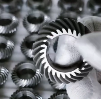
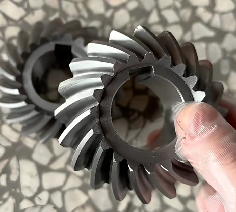
What lubrication types are used for helical gear systems and why?
Selecting an appropriate lubrication method plays a decisive role in the performance and service life of helical gears. In a helical gear system, lubrication is not a universal solution—it must be matched to operating conditions. Factors such as rotational speed, transmitted load, and working temperature all influence the final choice.
In practical Helical Gears Design, lubrication is treated as a core engineering decision because it directly affects friction control, heat dissipation, and wear resistance.
Common lubrication methods in helical gear systems
In most engineering applications, three primary lubrication types are used:
- Oil Splash/Bath lubrication– suited for moderate speed and load conditions
- Forced oil circulation systems– designed for high speed and heavy-duty operation
- Grease lubrication– used in low-speed or sealed environments
Each lubrication method serves a specific operational requirement, and selecting the wrong one can reduce efficiency or shorten gear life.
Oil Splash / Oil Bath lubrication
Oil splash (or oil bath) is one of the simplest and most widely used methods in helical gear systems. In this approach, gear teeth dip into an oil reservoir and distribute lubricant through rotation, coating adjacent components naturally.
This method is cost-efficient and works well in general-purpose machinery operating under moderate conditions. It requires minimal auxiliary equipment, which keeps system design straightforward.
However, at higher speeds, the oil can become overly agitated, creating a churning effect. This increases heat generation and power losses, which makes it unsuitable for high-performance or high-speed applications.
Forced oil circulation lubrication
Forced oil circulation uses an external pump to deliver filtered and often cooled oil directly to the gear mesh. This ensures a continuous and controlled lubricant supply, making it highly effective in demanding operating environments.
This system is particularly valuable when dealing with high loads and elevated speeds. It provides strong heat dissipation and maintains a stable lubricating film between gear teeth, especially important when pitch-line velocity is high.
While highly efficient, this method comes with increased system complexity, higher cost, and additional maintenance requirements due to pumps, filters, and cooling units.
Grease lubrication
Grease lubrication is commonly used in enclosed gear systems where oil circulation is not practical. It adheres well to surfaces and remains in place for long periods, reducing the need for frequent maintenance.
This makes it suitable for low-speed, intermittent operation, or machinery where access for servicing is limited.
The main limitation of grease is its poor heat transfer capability. Unlike oil-based systems, it does not effectively remove heat from the gear mesh, which restricts its use in higher-speed or heavily loaded conditions. Over time, grease can also harden, affecting performance.
Comparison of lubrication methods
- Oil Splash/Bath: simple structure, low cost, but limited cooling capacity and speed range
- Forced Oil Circulation: excellent cooling and lubrication stability, but higher cost and system complexity
- Grease Lubrication: low maintenance and good sealing performance, but weak heat dissipation
Choosing the right lubrication strategy is essentially a balance between performance requirements, thermal control, and system complexity. A well-matched lubrication method helps ensure stable operation, reduces wear, and extends the working life of helical gear systems under real operating conditions.
Why should you customize helical gears from Welleshaft?
Welleshaft is a China-based custom manufacturer specializing in high-precision helical gears, delivering tailored gear transmission solutions for global industrial customers. With long-term engineering experience and continuous process optimization, we support projects ranging from single-piece prototypes to large-scale production runs.
Our strength lies in combining advanced gear manufacturing technology with application-driven design support, ensuring every custom helical gear meets strict requirements for accuracy, durability, and performance across different industries.
High-precision manufacturing
We use precision grinding technology and advanced machining systems to produce high-accuracy helical gears while maintaining stable manufacturing quality and consistency. We are capable of achieving up to DIN Class 3 precision, making the gears suitable for demanding applications that require stable transmission performance and low deviation control.
Strong custom capability
We focus on flexible custom helical gear production, supporting large-scale customization across multiple parameters such as pitch diameter, tooth profile, module, material selection, and structural design.
With a maximum machining capacity of 2500mm pitch diameter, we can handle both standard and oversized gear requirements. We tailor our manufacturing process to meet different production needs, from single prototypes to batch production, while maintaining dimensional accuracy and consistent output.
Stringent quality control
Our quality team manages inspection through an in-house quality control system supported by advanced measurement equipment, including coordinate measuring machines and specialized gear inspection instruments. We use these technologies to verify dimensional accuracy, gear performance, and manufacturing consistency.
We conduct full-process verification covering dimensional accuracy, gear geometry, hardness testing, surface condition, noise evaluation, and defect detection. This ensures each custom helical gear meets defined engineering and performance standards before shipment.
Swift delivery
Our production team optimizes scheduling to reduce lead times throughout the entire manufacturing process, from raw material preparation to final inspection. We operate an extended shift system that enables continuous production and helps us meet urgent delivery requirements.
This structure helps reduce downtime and ensures timely completion even for complex or high-volume orders.
Personalized customization
We provide engineering-driven customization covering tooth count, module selection, helix angle, and dimensional specifications. Each design is adjusted according to the intended application to ensure proper fit and transmission efficiency.
This approach allows us to support diverse industrial applications with tailored gear solutions rather than standardized outputs.
Adaptation to complex transmission demands
Our engineers design helical gears to withstand demanding operating conditions, including high torque transmission, high-speed rotation, and angular load transfer. We optimize each gear design to deliver reliable performance in industrial applications.
Over time, we have supported more than 200 industrial clients across multiple sectors, helping solve transmission challenges where standard gear designs are not sufficient.
Performance optimization
Beyond basic manufacturing, we optimize gear performance through refined design adjustments such as tooth profile modification, helix angle optimization, and width control.
These improvements help enhance transmission efficiency, reduce operational noise, and extend service life under continuous working conditions.
High-quality manufacturing
Our production system integrates advanced machining equipment with standardized manufacturing procedures and multi-stage inspection control.
We monitor every manufacturing stage to maintain consistent helical gear geometry, mechanical strength, and surface quality. Our quality control process enables us to produce reliable helical gears that meet the performance requirements of industrial applications.
Technical support and collaboration
We work closely with clients during both design and production phases, providing engineering feedback and manufacturing recommendations.
This collaboration helps improve manufacturability, reduce potential design risks, and ensure the final product aligns with real operational requirements.
What are the most frequently asked questions about helical gears?
Are helical gears necessarily replaced with stainless steel when they rust?
Not always. Stainless steel is only necessary when helical gears are exposed to severe corrosion environments. In mild conditions, other materials with sufficient resistance can still perform effectively without needing a full material upgrade.
Is harder always better for helical gear materials?
Higher hardness does not automatically mean better performance. While increased hardness can improve wear resistance in helical gear materials, it may also reduce toughness, making the material more prone to cracking under impact. The optimal hardness level should be selected based on real operating conditions.
Are alloy steel and hardened steel the same material?
They are not the same. Alloy steel refers to a base material with added elements such as chromium or nickel to improve performance. Hardened steel, however, describes steel that has undergone heat treatment processes. In many cases, hardened steel components are made from alloy steel after processing.
Which helical gear materials do not require oil lubrication?
Gear designers commonly select nylon and POM for self-lubricating helical gear applications. These engineering plastics enable manufacturers to produce gears that operate without additional oil lubrication in low-load and low-speed environments, helping engineers reduce maintenance requirements.
How does the helix angle affect the performance of a helical gear?
The helix angle plays a key role in determining gear behavior. It affects contact ratio, smoothness, speed capacity, and axial thrust. A larger helix angle generally improves smooth operation and allows higher speeds, but it also increases axial force, requiring stronger bearing support in helical gear design.
What manufacturing methods are commonly used for helical gears?
Production of helical gears can involve several processes depending on precision and application requirements. Common methods include forging, casting, extrusion, powder metallurgy, hobbing, shaping, broaching, and milling. Each method is selected based on production volume, gear size, and required accuracy.
When should double helical or herringbone gears be used?
Gear designers select double helical and herringbone gears for high-load, high-efficiency applications where they need to control axial forces and maintain reliable power transmission.These designs are ideal for heavy-duty equipment such as marine propulsion systems, turbines, and industrial drives where vibration reduction and torque stability are essential.
How are post-manufacturing processes important for helical gears?
After initial production, helical gears often undergo finishing processes such as grinding, lapping, honing, shaving, or burnishing. These steps improve surface smoothness, dimensional accuracy, wear resistance, and operational lifespan, especially in high-speed or noise-sensitive applications.
This blog was provided by the Welleshaft Engineering Team, led by Mr. Xu, a mechanical engineering specialist with experience in gear transmission design and manufacturing. The team focuses on helical gear engineering, material selection, and process optimization, sharing practical insights to improve performance and reliability in real industrial applications.
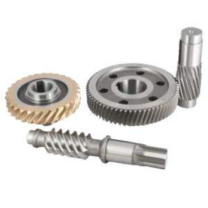
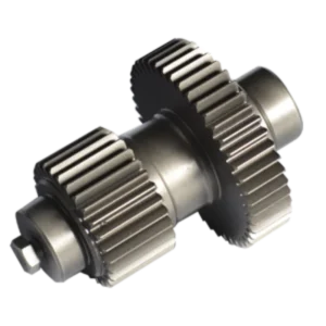
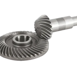
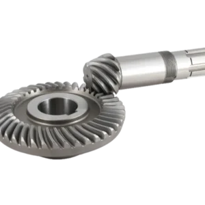
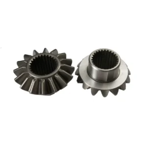
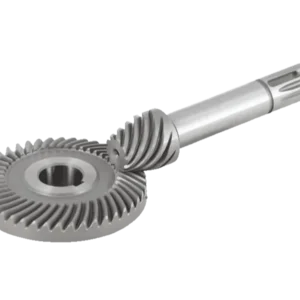
 Deutsch (Schweiz)
  English
  Português do Brasil
  Deutsch (Österreich)
  English (UK)
  English (Australia)
  English (New Zealand)
  Deutsch
  Français du Canada
  Français
  Français de Belgique
  Italiano
  English (South Africa)
  Português
  Español
  Español de México
  Español de Perú
  Español de Colombia
  العربية
  日本語
日本語  Русский
  한국어
한국어  Tiếng Việt
  ไทย
ไทย
Bewertungen
Es gibt noch keine Bewertungen.